the Creative Commons Attribution 4.0 License.
the Creative Commons Attribution 4.0 License.
 | 23 Apr 2020
Technical note: Nikon–TRACKFlow, a new versatile microscope system for fission track analysis
Gerben Van Ranst
Philippe Baert
Ana Clara Fernandes
Johan De Grave
We present Nikon–TRACKFlow, a new system with dedicated modules for automated microscope control and imaging for the fission track laboratory. It serves as a Nikon alternative for the Zeiss-based TrackWorks package from Autoscan Systems. Nikon–TRACKFlow is based on the Nikon Eclipse Ni-E motorised upright microscope and is embedded within Nikon NIS-Elements software. The system decouples image acquisition from analysis to decrease schedule stress of the microscope based on a number of automated user-friendly designs and protocols: (1) the well plate design that allows sequential scanning of multiple samples without the need of replacing the slide on the stage; (2) two protocols that are designed for the external detector method and the LA–ICP–MS fission track approach with tools for repositioning and calibration of the external detector; and (3) two other tools that are designed for automated point selection and scanning of large crystals, such as the Durango age standard and U-doped glass external detectors. In future versions, Nikon–TRACKFlow aims to step away from the dedicated system for fission track imaging towards a general high-throughput imaging system for Earth Sciences and other material-oriented sciences.
- Article
(5865 KB) - Full-text XML
-
Supplement
(5430 KB) - BibTeX
- EndNote


The fission track (FT) method (e.g. Malusá and Fitzgerald, 2019) places high requirements on its optical instruments and is further characterised by a high need for specific protocols and equipment regarding image acquisition and analysis, which are not always readily available from microscope producers. The FT method can thus benefit strongly from the implementation of technological improvements and automation of the process (Gleadow et al., 2019). The University of Melbourne was the first to develop a complete and comprehensive automated microscope system based on Zeiss microscopes and offers the only complete system of its kind (Gleadow et al., 2019). Their effort, which is commercialised by Autoscan Systems Pty Ltd, has become well established in many fission track laboratories around the world. However, while this readily available system exists, it must be noted that the market choice is limited for fission track laboratories. Specific preferences, such as the microscope brand, software specifications, style and specific protocols, can thus often not be (fully) met due to the limited options available on the market.
In this paper we introduce Nikon–TRACKFlow, a novel microscope system developed and optimised for the fission track laboratory, based on the Nikon Eclipse Ni-E motorised upright microscope (Fig. 1) and embedded within Nikon NIS-Elements software. As it was developed for the same purpose, it serves as a Nikon-based alternative for Autoscan TrackWorks, which is the microscope control and imaging package of the Autoscan Fission Track Studio Suite. Both systems have the aim to obtain maximum efficiency from a single microscope system, including to reduce schedule pressure. This is mainly done by decoupling image acquisition from the analysis, as one microscope can acquire images that can then be analysed on different computers. Although these systems pursue a similar goal and consequently contain similar automated tasks, they differ, amongst other things, in microscope brand, style and specific approach.

Figure 1Whole view of the Nikon–TRACKFlow system, which consists of the Nikon Eclipse Ni-E motorised upright microscope with DSC zoom body and Nikon DS-Ri2 camera. A PC or workstation and double displays are included for system management and data storage.
In this note we will first present a brief description of the system, after which we introduce the protocols which are implemented within Nikon–TRACKFlow. We finalise with a short conclusion and future perspectives. For a visual representation of the system, we refer to the short demonstration video (Van Ranst, 2020).
The system is based on the Nikon Eclipse Ni-E motorised upright microscope (Fig. 1; Nikon Corporation, 2019c), with the dedicated modules for apatite FT (AFT) research embedded within the Nikon NIS-Elements Advanced Research (AR) software package (Nikon Corporation, 2019b) with JOBS, a smart imaging design interface. NIS-Elements AR includes basic microscopy features and advanced image analysis functions (the Supplement). Nikon–TRACKFlow is embedded within NIS-Elements as to retain access to its versatile functionality on top of the specific features for fission track research.
We equipped our prototype with the Nikon DS-Ri2 camera (Nikon Corporation, 2019a), which has both a resolution to cover high to low-magnifications and has a large pixel size to obtain a high signal-to-noise ratio. High speed can be retained at high magnifications by changing analogue gain without introducing too much noise (Fig. 2). Although we recommend this camera to be combined with the system, it is also possible to equip the microscope with any other camera compatible with Nikon NIS-Elements (Nikon Corporation, 2020).

Figure 2Images created with the Nikon Eclipse Ni-E microscope and the DS-Ri2 camera, illustrating the effect of camera exposure time (ET) and analogue gain (AG). It can be observed that although there is an increase in the noise with higher AG, the image quality remains within acceptable values, in combination with shorter exposure times and thus faster refresh rates. All images were obtained using the 50× objective and diascopic illumination.
All protocols of Nikon–TRACKFlow are created using the JOBS module of the Nikon NIS-Elements package. Each protocol is built from a sequence of combined Nikon predefined tasks and newly implemented tasks programmed in the C-based Nikon API. These protocols are all based on the practical workflow for apatite FT (AFT) and include a large degree of adaptability, such as sample shape and size (Sect. 3.2), degree of automation, or illumination settings (Sect. 3.1). An overview of the available protocols and their workflow is provided in the Nikon–TRACKFlow flowchart (the Supplement). Figure 3 displays a condensed version of this flowchart.
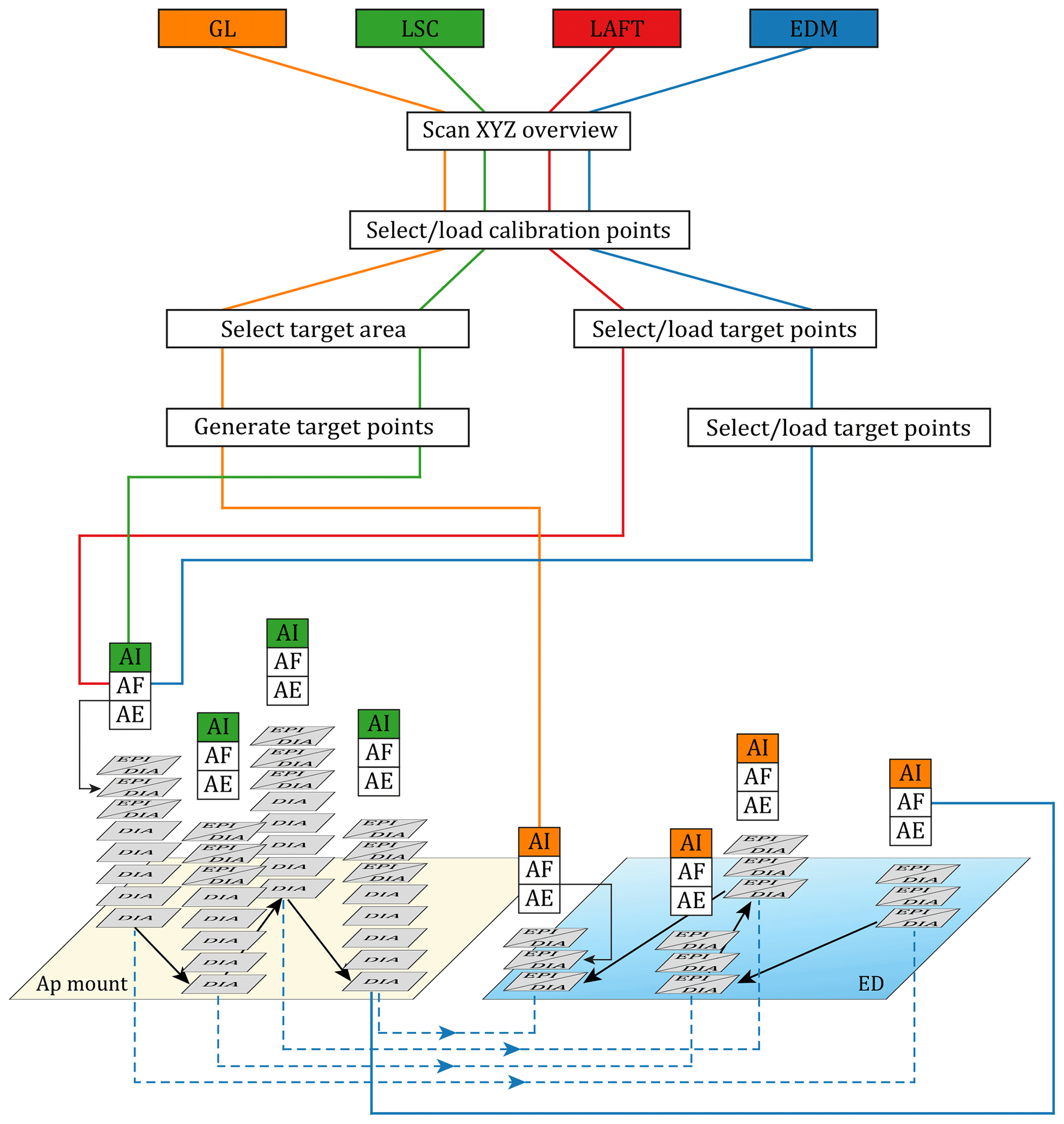
Figure 3Condensed version of the Nikon–TRACKFlow flowchart demonstrating the major steps of the different protocols. GL: glass tool, LSC: large single crystal tool, LAFT: LA–ICP–MS fission track tool, EDM: external detector method tool. AI: auto inspection, AF: autofocus, AE: auto exposure, EPI: episcopic, DIA: diascopic, Ap: apatite, ED: external detector.
3.1 Valve-based set-and-go protocol design
As can be deduced from the Nikon–TRACKFlow flowchart (the Supplement), each main protocol contains a workflow for a specific task. Structuring the modules around these workflows for fission track research in the Nikon environment forms the rationale behind the name of Nikon–TRACKFlow. Each main protocol in itself is built out of both serial and parallel sub-protocols, separated by on/off switches or “valves” that direct the flow (the Supplement). In this branched design, the operator starts the required main protocol, after which a choice menu is prompted. This menu also contains valves that direct the workflow by activating or deactivating sub-protocols according to the operator's preferences. Examples are the thickness of the mount, the number of calibration points (3–10), imaging/location storage, etc. Once the desired workflow is set, the system can operate without the need for operator intervention. An exception is the N–TF–EDM_s tool, which is designed for a mount and external detector (ED) to be attached to separate microscope slides, which thus requires replacing the slide during the protocol.
3.2 Well plate approach
Automation is most efficient when part of the protocol can be standardised, such as the locations of interest on a microscope slide. As such the automated microscope has a primary indication and knows where it needs to “look” for apatite grains or mount–ED homologous points. Microscope slides with such standardised positions or wells are frequently used in Life Sciences, where they are known as well plates. In this view, each apatite mount or external detector occupies the place of a well, with the microscope slide on which they are attached serving as a well plate.
Although wells are often physical pits, the well positions here are simple markings on a glass slide, which can easily be made with a stencil or obtained from the FT laboratory of Ghent University (Fig. 4). Nikon–TRACKFlow comes with a standard well plate for four EDM mounts and four EDs and a well plate of either two or three wells for LA–ICP–MS FT (LAFT) mounts. It is, however, still possible to generate new well plates, fitting the standard preparation style of different laboratories. Geometrical limitations of the wells are set by the XY limits of the stage and the diameter of the high-magnification objective lenses in the case where a thin ED is placed on the stage at the same time as the 1 mm thick mount. The problem of difference of thickness can, however, be solved by fixing small 1 mm thick glass slides on the main glass slide at the position of the EDs (e.g. Kohn et al., 2019).
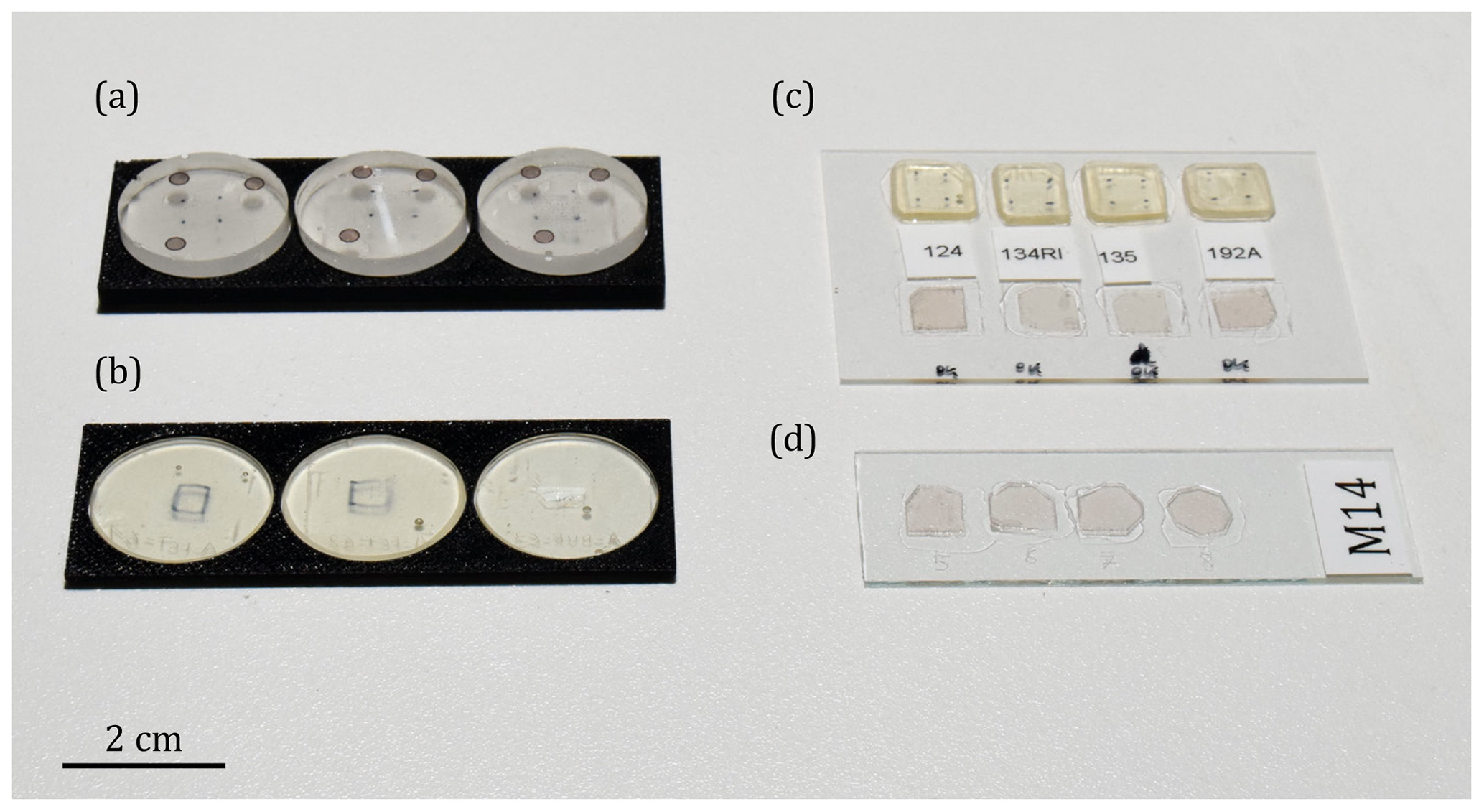
Figure 4Standard Nikon–TRACKFlow microscopy slides. (a) Thick 3-mount adaptor slide for thick (∼5 mm) 25 mm mounts, usually for LAFT. (b) Thin 3-mount adaptor slide for thin (1 mm) 25 mm mounts. 25 mm mounts can be placed in the adaptor slides for imaging and are removed afterwards. (c) Standard EDM Nikon–TRACKFlow (52×76 mm) glass slide. It is possible to raise thin micas to the level of the apatite mounts by attaching a standard microscopy glass slide (26×76 mm) to the bottom of the main slide using nail polish. (d) Standard EDM Nikon–TRACKFlow (26×76 mm) glass slide. Used for U-doped glass EDs or separate mounting of apatite mounts and EDs.
3.3 Transformation engine
Coordinate transformation is an essential tool for AFT, when using the ED method (EDM; Fleischer et al., 1964, 1975) by means of an automated microscope stage (Dumitru, 1993; Gleadow et al., 1982; Smith and Leigh-Jones, 1985). Homologous points to calculate transformation parameters are usually produced by pin pricks, co-embedded zircons or copper TEM grids (Smith and Leigh-Jones, 1985).
Nikon–TRACKFlow makes use of a basic 2D Helmert transformation with a least-squares regression. This Helmert transformation is preceded by a reflection along a vertical axis to deal with the flipping of the ED as to place it in tracks-up position. The Helmert transformation can cover most coordinate differences that are met in the application.
Nikon–TRACKFlow gives the operator the option to select up to 10 homologous point couples, which can be stored for later use. After transformation the system displays the average X and Y residuals as a metric for the transformation parameter quality. As it is common practice to refine the primary alignment using mineral grains (Kohn et al., 2019), the system offers the option to perform a secondary selection of homologous points. The primary calibration is then used as a guide to find homologous points of manually preselected points, such as zircons or apatite grains or automatically generated points selected from the apatite target list. In this case images are acquired from these fine calibration points on the mount, which allows the operator to select the homologous position inside the induced track cloud. We state, however, that grains with U zonation or low-U content may still be problematic for this grain-based approach (e.g. Jonckheere et al., 2003).
The order in which two homologous sets of calibration points are selected can be arbitrary, so the operator is not required to retain the same order. This is due to the sorting algorithm in Nikon–TRACKFlow that is executed before the calculation of transformation parameters. All points are first sorted according to a scanning line that crosscuts the barycentre of the calibration points and rotates in anticlockwise direction. As this line segment starts horizontally in the direction of the x axis, calibration points should not be chosen in the middle-left section of the mount. On the ED the scanning sweep is reflected horizontally. Allowing an arbitrary order of selecting points is also convenient for when these points are retrieved automatically through image analysis.
3.4 Scout pre-protocol
The scout pre-protocol embeds the Nikon NIS-Elements Large Image Stitching function as a sub-protocol. The tool provides a zoomable “map” of each mount of the slide or well plate, which can be used to navigate each sample (Fig. 5).

Figure 5Illustration of the “XYZ Overview” with a large image composed of stitched tiles. The image contains a thin slab of a Durango crystal and four co-embedded zircons as calibration points (indicated with arrows). The green diamonds are positions automatically generated by the N–TF–LSC protocol with automatic crystal detection and automatic inspection enabled. Points near the crack in the centre were not retained by the automatic inspection due to insufficient luminosity caused by the crack.
3.5 Imaging protocols
3.5.1 Large single crystal tool (N–TF–LSC)
The main function of the large single crystal (LSC) tool is to automatically create a regular grid of points inside large apatite crystals, such as the Durango age standard (Fig. 5). These points represent digital non-overlapping fragments of the grain, i.e. samples from the entire extent of the grain. The tool automatically defines the bounding box of the crystal based on the extent of the darker pixels defining its rim. A regular grid is then created within the bounding box according to the operator's preset specifications. A warning is prompted if these specifications would produce overlap. The automatic inspection verifies whether the generated points are either crystal, epoxy or contain large cracks. Only clear crystal points are retained for imaging and their coordinates exported. Both setting the bounding box and inspection can be performed manually as well. The tool can be used for both the standard zeta calibration (Hurford, 1990; Hurford and Green, 1983) and for the absolute calibration (Jonckheere, 2003). As an indication, our prototype system had a run of 55 min for a Durango scan, including set-up, automated crystal detection, grid generation (148 points), point-by-point-inspection and imaging (EPI + DIA z stack). Using recoordination, a second scan of the same crystal does not require a new crystal detection, point generation or point inspection. Processing and image storage speed is also dependent on the attached computer.
3.5.2 Glass tool (N–TF–GL)
The glass tool is similar to the LSC tool but optimised for the EDs of dosimeter glasses used in the EDM approach. The main difference is that it is not possible to determine the bounding box around the induced tracks automatically, so this action needs to be performed manually on a presented large image. Automatic inspection of whether a generated point contains tracks is embedded in the protocol. It is also possible to include recoordination points for each glass ED. As such, each generated grid of points inside the glass region can be reloaded for the scanning of the same glass EDs in other irradiation packages. Coordinate transformation is therefore included in the glass tool for this purpose.
3.5.3 Mount–ED tool (N–TF–EDM_s/m)
The mount–ED or EDM tool comes in two versions: single mount (EDM_s) or multi-mount (EDM_m). The only difference between the two is that the single mount version is designed for the scanning of one mount and ED (mounted on the same or different glass slides) at arbitrary locations and the multi-mount version is intended for mounts and their EDs mounted on a well plate. The latter can thus scan up to four samples in a single run. A single mount–mica couple (20 points) was imaged in 24 min, including protocol set-up and autofocus for each point. It should also be noted that automated imaging systems, in contrast to a human analyst, can work around the clock.
3.5.4 LAFT tool (N–TF–LAFT)
The LAFT tool is intended for the scanning of grains for the LA–ICP–MS based method (e.g. Cogné et al., 2019; Hasebe et al., 2004). It allows for the registration of recoordination points, recoordination of existing coordinates, and the scanning of thin or thick (∼5 mm) mounts locked in a well plate. If the option is selected, illumination is automatically adapted for thick mounts so as to deal with the mismatch of the focal plane level with the optimal distance of the condenser lens for this type of sample.
Nikon–TRACKFlow is a new system for (semi)automated microscopy, which broadens the market for fission track laboratories. It comes with user-friendly modules for specific tasks, which exhibit adaptable degrees of automation.
The system presented here is the current working version of Nikon–TRACKFlow. Continuing developments are, however, still being made for next version of the system. These mainly focus on a more extensive automation and upscaling to high-throughput imaging, e.g. by making use of the Märzhäuser Slide Express 2. Further automation is achieved by training image analysis recipes to be applicable to different samples. These recipes can then be embedded into the current protocols and enable the system to make decisions without intervention of the operator. A future objective is also to reach beyond the application of fission track thermochronology and to evolve to a general high-throughput system for Earth Sciences and other material-oriented sciences.
Nikon–TRACKFlow is licensed from Ghent University to Nikon. The full software package for Nikon–TRACKFlow is based on the NIS-Elements AR software suite (Nikon) and can be purchased through Nikon.
A video supplement is provided with this article and can be found at https://doi.org/10.17632/yf5dccxcww.1 (Van Ranst, 2020). This video shows a short demonstration of the set-up and scanning of a single sample using the N–TF–EDM_m protocol.
The supplement related to this article is available online at: https://doi.org/10.5194/gchron-2-93-2020-supplement.
Conceptualisation, investigation, software development and validation, visualisation, and writing of the original draft were done by GVR. PB provided technical support, software support and reviewed the article. ACF provided technical support. JDG acquired funding and resources, supervised the work, and reviewed the article.
The authors declare the following potential conflicts of interest: Nikon–TRACKFlow is licensed from Ghent University to Nikon as a commercial product. Philippe Baert and Ana Clara Fernandez are employed at Nikon. Note that all funding was obtained from the Ghent University Special Research Fund.
Our gratitude goes out to Simon Nachtergaele, who performed the first tests of the protocols both during the development and in their final version. His contributions have helped us to improve the intuitive and user-friendly nature of the workflow. We also want to thank the handling associate editor, Pieter Vermeesch, and reviewers Hideki Iwano, Ian Duddy and Andrew Gleadow for their constructive reviews and for their recommendations, which have strongly improved both the quality and message of our article.
This research has been supported by the Special Research Fund (Ghent University) (grant no. BOF 01N03915).
This paper was edited by Pieter Vermeesch and reviewed by Hideki Iwano and Andrew Gleadow.
Cogné, N., Chew, D. M., Donelick, R. A., and Ansberque, C.: LA-ICP-MS apatite fission track dating: A practical zeta-based approach, Chem. Geol., 531, 119302, https://doi.org/10.1016/j.chemgeo.2019.119302, 2019.
Dumitru, T. A.: A new computer-automated microscope stage system for fission-track analysis, Nucl. Tracks Rad. Meas., 21, 575–580, https://doi.org/10.1016/1359-0189(93)90198-I, 1993.
Fleischer, R. L., Price, P. B., and Walker, R. M.: Fission-track ages of zircons, J. Geophys. Res., 69, 4885, https://doi.org/10.1029/JZ069i022p04885, 1964.
Fleischer, R. L., Price, P. B., and Walker, R. M. R. M.: Nuclear Tracks in Solids: Principles and Applications, University of California Press, Berkeley, 1975.
Gleadow, A. J. W., Leigh-Jones, P., Duddy, I. R., and Lovering, J. F.: An automated microscope stage system for fission track dating and particle track mapping, in: Workshop on fission track dating, Fifth international conference on geochronology, Cosmochronology and isotope geology, Nikko Japan, 22–23, 1982.
Gleadow, A. J. W., Kohn, B. P. and Seiler, C.: The Future of Fission-Track Thermochronology, in: Fission-Track Thermochronology and its Application to Geology, edited by: Malusà, M. G. and Fitzgerald, P. G., Springer International Publishing, Cham., 393 pp., 2019.
Hasebe, N., Barbarand, J., Jarvis, K., Carter, A., and Hurford, A. J.: Apatite fission-track chronometry using laser ablation ICP-MS, Chem. Geol., 207, 135–145, https://doi.org/10.1016/j.chemgeo.2004.01.007, 2004.
Hurford, A. J.: Standardization of fission track dating calibration: Recommendation by the Fission Track Working Group of the I.U.G.S. Subcommission on Geochronology, Chem. Geol., 80, 171–178, https://doi.org/10.1016/0168-9622(90)90025-8, 1990.
Hurford, A. J. and Green, P. F.: The Zeta age calibration of fission-track dating, Isot. Geosci., 1, 285–317, https://doi.org/10.1016/S0009-2541(83)80026-6, 1983.
Jonckheere, R. C.: On the densities of etchable fission tracks in a mineral and co-irradiated external detector with reference to fission-track dating of minerals, Chem. Geol., 200, 41–58, https://doi.org/10.1016/S0009-2541(03)00116-5, 2003.
Jonckheere, R. C., Ratschbacher, L., and Wagner, G. A.: A repositioning technique for counting induced fission tracks in muscovite external detectors in single-grain dating of minerals with low and inhomogeneous uranium concentrations, Radiat. Meas., 37, 217–219, https://doi.org/10.1016/S1350-4487(03)00029-5, 2003.
Kohn, B. P., Chung, L., and Gleadow, A. J. W.: Fission-Track Thermochronology and its Application to Geology, edited by: Malusà, M. G. and Fitzgerald, P. G., Springer International Publishing, Cham., 2019.
Malusá, M. G. and Fitzgerald, P. G. (Eds.): Fission-Track Thermochronology and its Application to Geology, Springer International Publishing, Cham., 2019.
Nikon Corporation: Digital Cameras for Microscopes Brochure, available at: https://d33b8x22mym97j.cloudfront.net/phase4/literature/Brochures/2ce-mpaj-1.pdf?mtime=20190319105015 (last access: 10 March 2020), 2019a.
Nikon Corporation: Imaging Software NIS Elements Brochure, Japan, available at: https://d33b8x22mym97j.cloudfront.net/phase4/literature/Brochures/2ce-mpcj-2.pdf?mtime=20191218090935 (last access: 10 March 2020), 2019b.
Nikon Corporation: Upright Microscope for Research ECLIPSE Ni/Ci Brochure, available at: https://d33b8x22mym97j.cloudfront.net/phase4/literature/Brochures/2ce-mqvj-1-2.pdf?mtime=20190705101323 (last access: 10 March 2020), 2019c.
Nikon Corporation: Nikon | NIS-Elements – Table of features, available at: https://www.nikon.com/products/microscope-solutions/lineup/img_soft/nis-elements/table_ of_features.htm, last access: 5 March 2020.
Smith, M. J. and Leigh-Jones, P.: An automated microscope scanning stage for fission-track dating, Nucl. Tracks Rad. Meas., 10, 395–400, https://doi.org/10.1016/0735-245X(85)90129-2, 1985.
Van Ranst, G.: Nikon-TRACKFlow demonstrations, Mendeley Data, https://doi.org/10.17632/yf5dccxcww.1, 2020.