the Creative Commons Attribution 4.0 License.
the Creative Commons Attribution 4.0 License.
 | 03 Apr 2023
Chemical abrasion: the mechanics of zircon dissolution
Isabel Koran
Blair Schoene
Richard A. Ketcham
Chemical abrasion is a technique that combines thermal annealing and partial dissolution in hydrofluoric acid (HF) to selectively remove radiation-damaged portions of zircon crystals prior to U–Pb isotopic analysis, and it is applied ubiquitously to zircon prior to U–Pb isotope dilution thermal ionization mass spectrometry (ID-TIMS). The mechanics of zircon dissolution in HF and the impact of different leaching conditions on the zircon structure, however, are poorly resolved. We present a microstructural investigation that integrates microscale X-ray computed tomography (µCT), scanning electron microscopy, and Raman spectroscopy to evaluate zircon dissolution in HF. We show that µCT is an effective tool for imaging metamictization and complex dissolution networks in three dimensions. Acid frequently reaches crystal interiors via fractures spatially associated with radiation damage zoning and inclusions to dissolve soluble high-U zones, some inclusions, and material around fractures, leaving behind a more crystalline zircon residue. Other acid paths to crystal cores include the dissolution of surface-reaching inclusions and the percolation of acid across zones with high defect densities. In highly crystalline samples dissolution is crystallographically controlled with dissolution proceeding almost exclusively along the c axis. Increasing the leaching temperature from 180 to 210 ∘C results in deeper etching textures, wider acid paths, more complex internal dissolution networks, and greater volume losses. How a grain dissolves strongly depends on its initial radiation damage content and defect distribution as well as the size and position of inclusions. As such, the effectiveness of any chemical abrasion protocol for ID-TIMS U–Pb geochronology is likely sample-dependent. We also briefly discuss the implications of our findings for deep-time thermochronology.
- Article
(20414 KB) - Full-text XML
- Companion paper
-
Supplement
(2671 KB) - BibTeX
- EndNote


Zircon U–Pb dating by isotope dilution thermal ionization mass spectrometry (ID-TIMS) produces high-precision dates that the Earth science community depend on to calibrate geologic time (Bowring and Schmitz, 2003; Schoene, 2014). Zircon crystals affected by radiation damage – caused by alpha recoil events in the 238U, 235U, and 232Th decay series and the spontaneous fission of 238U (Holland and Gottfried, 1955; Weber et al., 1990; Murakami et al., 1991; Meldrum et al., 1998; Trachenko et al., 2002; Ewing et al., 2003) – can lose radiogenic Pb – or more rarely U – by diffusion, leaching, or recrystallization, compromising the accuracy of U–Pb ages (Mezger and Krogstad, 1997; Nasdala et al., 1998; Geisler et al., 2002). Open-system behavior can sometimes be identified graphically on a concordia diagram when there is a mismatch between the and isotopic clocks, but sometimes discordia lines closely track concordia, making Pb loss difficult to detect, thereby complicating age interpretations from zircon datasets (Mezger and Krogstad, 1997; Schoene, 2014).
Chemical abrasion, a technique that combines thermal annealing to induce partial structural recovery and leaching in hydrofluoric acid (HF) to selectively remove soluble radiation-damaged portions of crystals prior to U–Pb isotopic analysis, revolutionized the field's ability to date zircon crystals affected by open-system behavior (Mundil et al., 2004; Mattinson, 2005, 2011). Still, many chemically abraded U–Pb zircon datasets exhibit anomalously young, concordant dates that are often attributed to residual Pb loss or, in rare instances older, reversely discordant dates (Mattinson et al., 1996; Davydov et al., 2010; Schoene et al., 2010a; Schmitz and Davydov, 2012; Meyers et al., 2012). Undetected open-system behavior can potentially bias or lead to the assignment of inappropriate age uncertainties in critical geologic interpretations for which ∼ 100 ka precision and accuracy matter such as correlations between terrestrial flood volcanism and biotic crises or between biostratigraphic and radioisotopic calibrations constructed to study key climate transitions in Earth history (Schoene et al., 2010a; Schmitz and Davydov, 2012). This ongoing challenge has recently prompted the ID-TIMS U–Pb community to more closely evaluate how different chemical abrasion protocols – which can vary considerably both within and between individual laboratories – affect geochronological results (Huyskens et al., 2016; Widmann et al., 2019) and to explore different frameworks for interpreting crystallization ages and uncertainties in complex U–Pb datasets (e.g., Schoene, 2014).
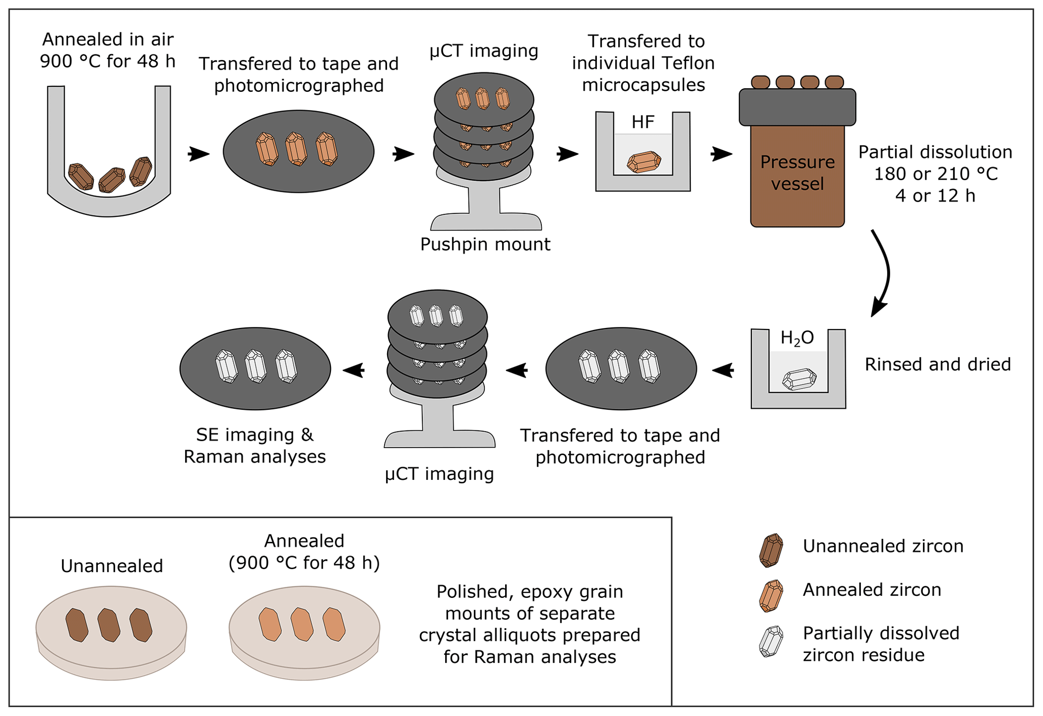
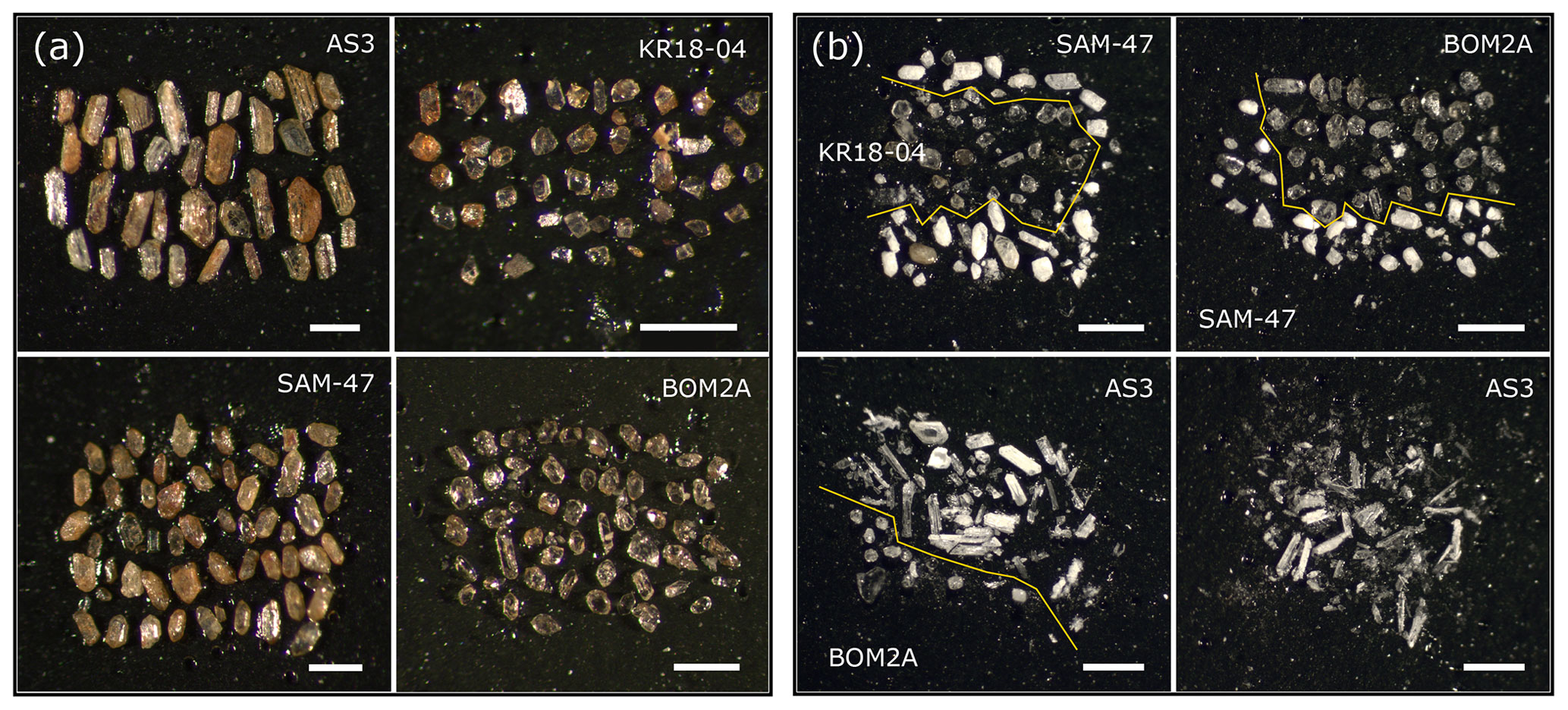
Figure 2Color reflected-light photomicrographs of zircon crystals mounted on tape for µCT imaging. (a) Photomicrograph of annealed grains prior to chemical abrasion. (b) Photomicrograph of zircon residues following chemical abrasion. The after images illustrate how chemical abrasion anneals color centers in grains and renders grains colorless.
Despite the nearly universal acceptance of chemical abrasion, the mechanics of zircon dissolution during acid digestion are poorly documented in the literature. Previous work has demonstrated that acid dissolves U-rich rims and can reach the interior of some grains to preferentially dissolve U-rich zones in zircon cores (Mundil et al., 2004; Mattinson, 2005, 2011). However, no study to date has systematically documented zircon dissolution textures given a range of zircon types and leaching conditions, nor leveraged such findings to gain a mechanistic understanding of the microstructural processes that occur during partial dissolution in HF. Such an understanding would improve Pb-loss mitigation efforts and help ensure the accuracy of high-precision ID-TIMS zircon U–Pb dates. In this study, we present the first three-dimensional (3D) view of zircon dissolution based on microscale X-ray computed tomography data (µCT) acquired before and after leaching in HF. We evaluate zircon crystals from different geological settings with different degrees of radiation damage treated at different leaching conditions (180 ∘C vs. 210 ∘C, 4 h vs. 12 h). These data are paired with secondary electron images of etched grain surfaces and Raman spectral data used to track changes in zircon crystallinity. In addition to achieving valuable new insights into the mechanics of zircon dissolution, our µCT data reveal exciting opportunities for quickly and non-destructively imaging radiation damage zoning in zircon in 3D, which has broader implications for zircon chronology.
2.1 Samples
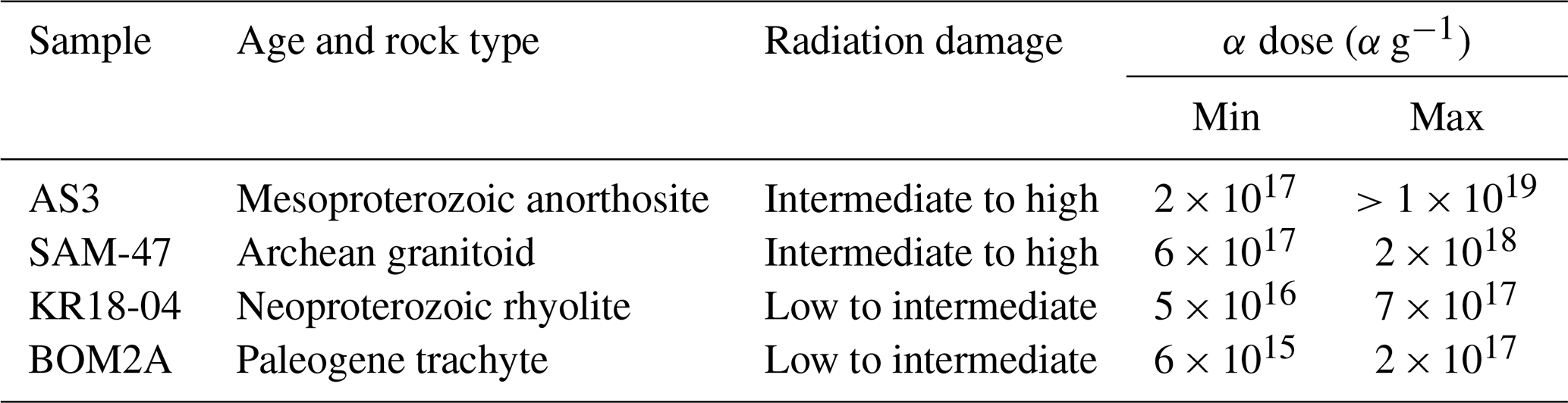
Our study focuses on four zircon samples (AS3, SAM-47, KR18-04, and BOM2A) that together span nearly the full radiation damage spectrum (Table 1). AS3 is an intermediate- to high-damage sample from the Mesoproterozoic Duluth Complex anorthositic series, emplaced during the North American Midcontinent Rift (Paces and Miller, 1993; Schmitz et al., 2003; Takehara et al., 2018; Swanson-Hysell et al., 2020). The sample of AS3 used in this study is the same as that studied by Takehara et al. (2018), which was collected from the same locality as that of Paces and Miller (1993) (92∘09′32.4′′, 46∘45′43.4′′). AS3 crystals are coarse-grained, orange to orangish brown, and fractured. Most grains are tabular prisms or anhedral shards, and many show evidence of hydrothermal alteration (Takehara et al., 2018). SAM-47 is an intermediate- to high-damage Archean (3.32–3.29 Ga) sample from the Corunna Downs Granitic Complex of the Emu Pools Supersuite in the eastern Pilbara Craton (−21∘24′29.01′′, 119∘46′21.03′′) (Barley and Pickard, 1999; Smithies et al., 2003; van Kranendonk et al., 2007). Grains are euhedral, brown, and translucent. KR18-04 is an intermediate- to low-damage sample from a Neoproterozoic rhyolite body associated with the glaciolacustrine Konnarock Formation of Virginia, USA (MacLennan et al., 2020) (36∘41′47.95′′, 81∘24′22.08′′). Grains are small, transparent, pink–orange, and prismatic. BOM2A is our lowest-damage sample from a Paleocene trachyte dike in Mumbai, India, associated with rifting following the main phase of Deccan Traps volcanism (Basu et al., 2020). Crystals are small, transparent, colorless, and prismatic.
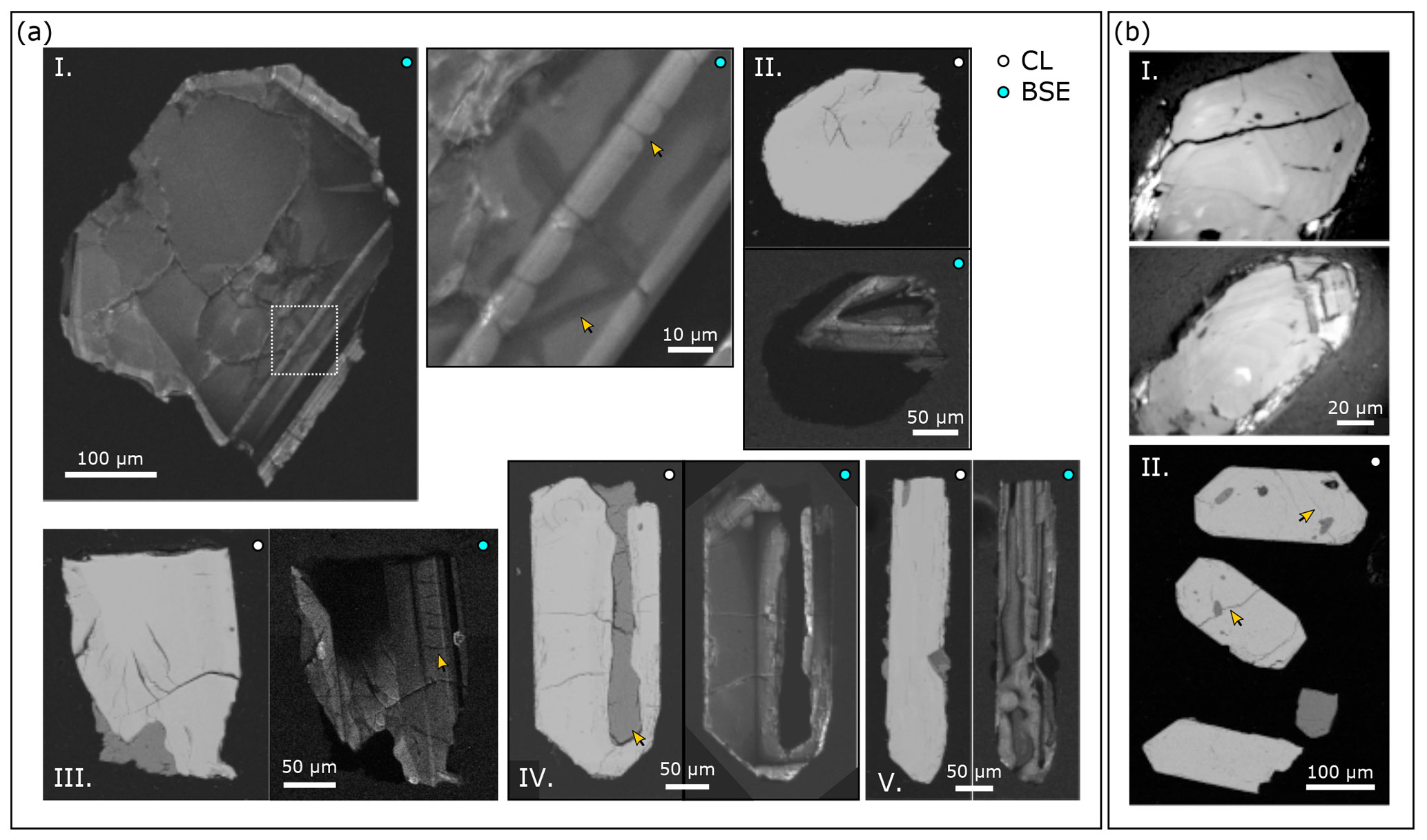
Figure 3Representative images of annealed AS3 and SAM-47 zircons that have not been treated by chemical abrasion. (a) SEM images of annealed AS3 zircon. (I) A zircon with simple growth zoning. Arrows highlight dark hydrothermal alteration zones associated with fine-scale fractures. Some fractures cross-cut compositional zones. (II) Zircon with an unfractured high-damage, CL-black rim and a fractured core. (III) Zircon with a row of fractures that cross-cuts a zone. (IV) Zircon with a large melt inclusion oriented parallel to the c axis. (V) Zircon with convolute growth zoning. (b) Representative images of annealed SAM-47 zircon. (I) Reflected-light images showing fine-scale concentric growth zoning. (II) BSE images showing that some grains are finely fractured. Some of these fractures pass though mineral inclusions (arrows).
Aliquots of unannealed and annealed (900 ∘C for 48 h) grains from each of the four zircon samples were set aside at the start of the study, mounted, polished, and characterized using Raman spectroscopy to quantify the degree of radiation damage present in each sample, as key bands in the zircon Raman spectrum broaden predictably with increasing damage (Nasdala et al., 2001; Palenik et al., 2003; Váczi and Nasdala, 2017). Annealed grain mounts were also imaged using optical microscopy, cathodoluminescence (CL) imaging, and/or backscattered electron (BSE) imaging to characterize growth textures for each sample (Fig. 1).
2.2 Workflow for partial dissolution experiments
A diagram depicting our experimental workflow is presented in Fig. 1. Separate aliquots of the four zircon samples were annealed in quartz crucibles in air at 900 ∘C for 48 h in a box furnace. Annealing conditions follow the recommendations of Huysken et al. (2016), who demonstrated that hotter annealing temperatures likely restore crystallinity to domains affected by Pb loss. Annealing durations within the ID-TIMS U–Pb community typically range between 48 and 60 h (Huysken et al., 2016; Widmann et al., 2019). Annealing studies of radiation damage in zircon demonstrate that annealing only weakly depends on heating duration after the first few hours of heating (Ginster et al., 2019, their Fig. 1). Thus, the difference between 48 and 60 h is not expected to significantly change zircon crystallinity or affect chemical abrasion outcomes.
Annealed grains were mounted on sticky tape (∼ 6 mm diameter circles fashioned using a hole punch) and imaged using optical microscopy. The four sticky tape mounts were then stacked on top of a pushpin and loosely secured with tape for µCT imaging (Cooperdock and Stockli, 2016). After imaging, grains were removed from the sticky tape and transferred to individual Teflon microcapsules for leaching in concentrated HF in a Parr Instrument Company pressure digestion vessel at 180 or 210 ∘C for a duration of 4 or 12 h. The chosen temperatures bracket the range commonly used for chemical abrasion by the ID-TIMS U–Pb community (Huyskens et al., 2016; Widmann et al., 2019). Leaching durations were selected based on the sample's initial radiation damage content. Most intermediate- to high-damage zircon crystals (AS3 and SAM-47) were chemically abraded at shorter durations to ensure that intact zircon residues remained (as opposed to dust), although one subset of AS3 grains were leached at 180 ∘C for the full 12 h. The intermediate- to low-damage samples (KR18-04 and BOM2A) maintained structural integrity over longer leaching durations, so grains were leached for the full 12 h period commonly used for chemical abrasion.
After partial dissolution, residues – the portions of zircon crystals that survive chemical abrasion – were rinsed in Milli-Q water, dried down, and carefully transferred to fresh sticky tape. Mounted residues were then re-imaged using optical microscopy and µCT to generate a “before” and “after” imagery dataset. Microphotographs of annealed grains and chemically abraded zircon residues are presented in Fig. 2. Following µCT, residue mounts were carbon-coated, and secondary electron (SE) images of residue surfaces were acquired using a scanning electron microscope (SEM). Raman spectra were measured for a subset of zircon residues to characterize samples' crystallinities.
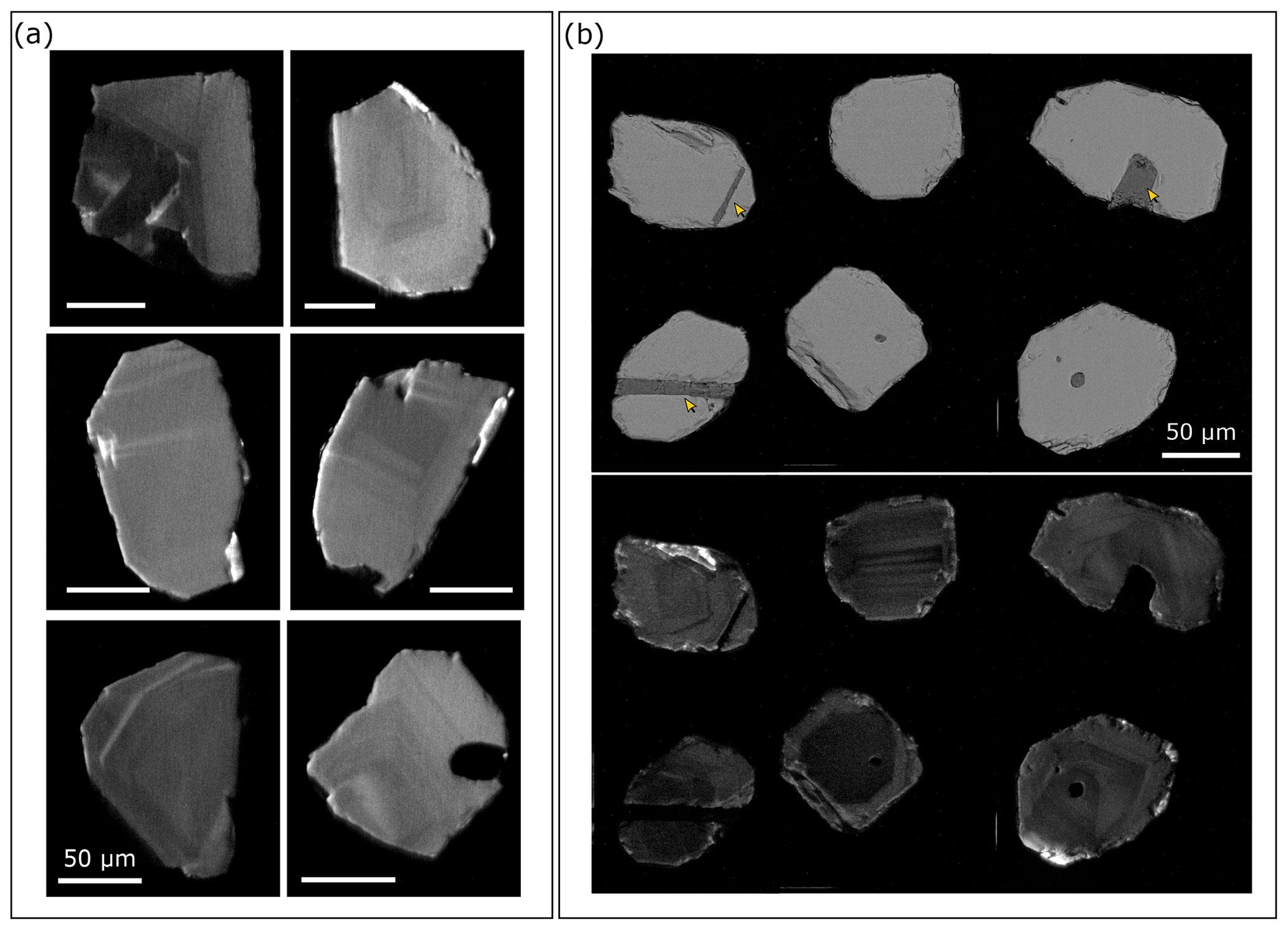
Figure 4Representative images of annealed KR18-04 and BOM2A zircons that have not been treated by chemical abrasion. (a) CL images of annealed KR18-04 zircon with fine concentric or broad, faint growth patterns. All scale bars are 50 µm. (b) Representative BSE (top) and CL (bottom) images of annealed BOM2A zircon showing broad concentric growth zoning. Arrows highlight the frequent occurrence of apatite inclusions.
2.3 Instrumentation and analyses
Chemical abrasion was carried out using equipment and clean lab space at Princeton University. CL and BSE images of polished mounts were acquired using the XL30 FEG SEM at the PRISM Imaging and Analysis Center at Princeton University equipped with a mini-Gatan CL detector and a semiconductor BSE detector. Most images were acquired using a 10 kV accelerating voltage, 10 mm working distance, and spot size 5. SE images of chemically abraded zircon residues were captured using the Quanta FEG 200 Environmental-SEM, also at the PRISM Imaging and Analysis Center. This system is equipped with a Schottky field emission gun and Everhart–Thornley secondary electron detector. SE images were acquired using low-vacuum mode (∼ 0.4 to 0.8 Torr) to minimize charging due to sample topography. Scans used a 10 kV accelerating voltage, 10 to 10.5 mm working distance, and spot size 4 or 5.
All X-ray computed tomography data were collected at the High-Resolution X-ray Computed Tomography Facility at the University of Texas at Austin using a Zeiss Xradia 620 Versa. Measurements were made with X-rays set to 120 kV and 15 W and prefiltered with the LE3 filter. For each scan 2401 views were obtained over a 360∘ rotation at 4 s per view on the 4× detector. The 16-bit TIFF images were reconstructed at 1.62 µm per voxel using a beam-hardening correction setting of 1.8 in the Xradia Reconstructor software. All 2D and 3D visualizations and quantitative measurements were made using Object Research Systems (ORS) Dragonfly software. Crystallographic dimensions for BOM2A and KR18-04 were measured using the ruler function. Volume estimates for these two samples were made using the software's “Upper OTSU” segmentation function. This function differentiates zircon from inclusions, dissolution features, and background (tape or air) based on grayscale intensity. Total volume is calculated by adding the number of selected high-intensity zircon voxels together. The volume of one voxel is ∼ 4.25 µm3.
Raman spectra were acquired using the Horiba LabRAM Evolution Raman spectrometer in the High-Pressure Mineral Physics Laboratory at Princeton University. Measurements were made using either a 632.81 or 532 nm diode laser. The laser power to the sample surface was ∼ 8.5 to 17 mW and ∼ 7.5 to 30 mW for the red and green lasers, respectively. The instrument was calibrated daily using the silicon 520.7 cm−1 Raman band and the automated protocol implemented within the Horiba Scientific LabSpec6 software (Itoh and Shirono, 2020). Additionally, a quartz reference spectrum was acquired daily to verify the accuracy of measured peak positions (Krishnam, 1945). All measurements were made using an 1800 g mm−1 grating, a 100 µm slit, a 400 to 100 µm confocal pin hole, and either an Olympus 100×/0.9 na lens or Mitutoyo 50× or 20× long working distance objective lens.
This setup has a spectral resolution better than 2 cm−1 and a spatial resolution of <1 to ∼ 5 µm. Polynomial background subtractions and Gaussian–Lorentzian peak fits were made using LabSpec6 software. Peak widths have estimated uncertainties on the order of 10 % (2σ) based on tests of measurement and peak fit reproducibility. All reported peak widths (full width at half maximum, FWHM) have been corrected for instrumental broadening following the approach of Váczi (2014). A Raman spectrum for a synthetic zircon grown using a Li-Mo flux method (Hanchar et al., 2001) was acquired as a loose analog for undamaged zircon.
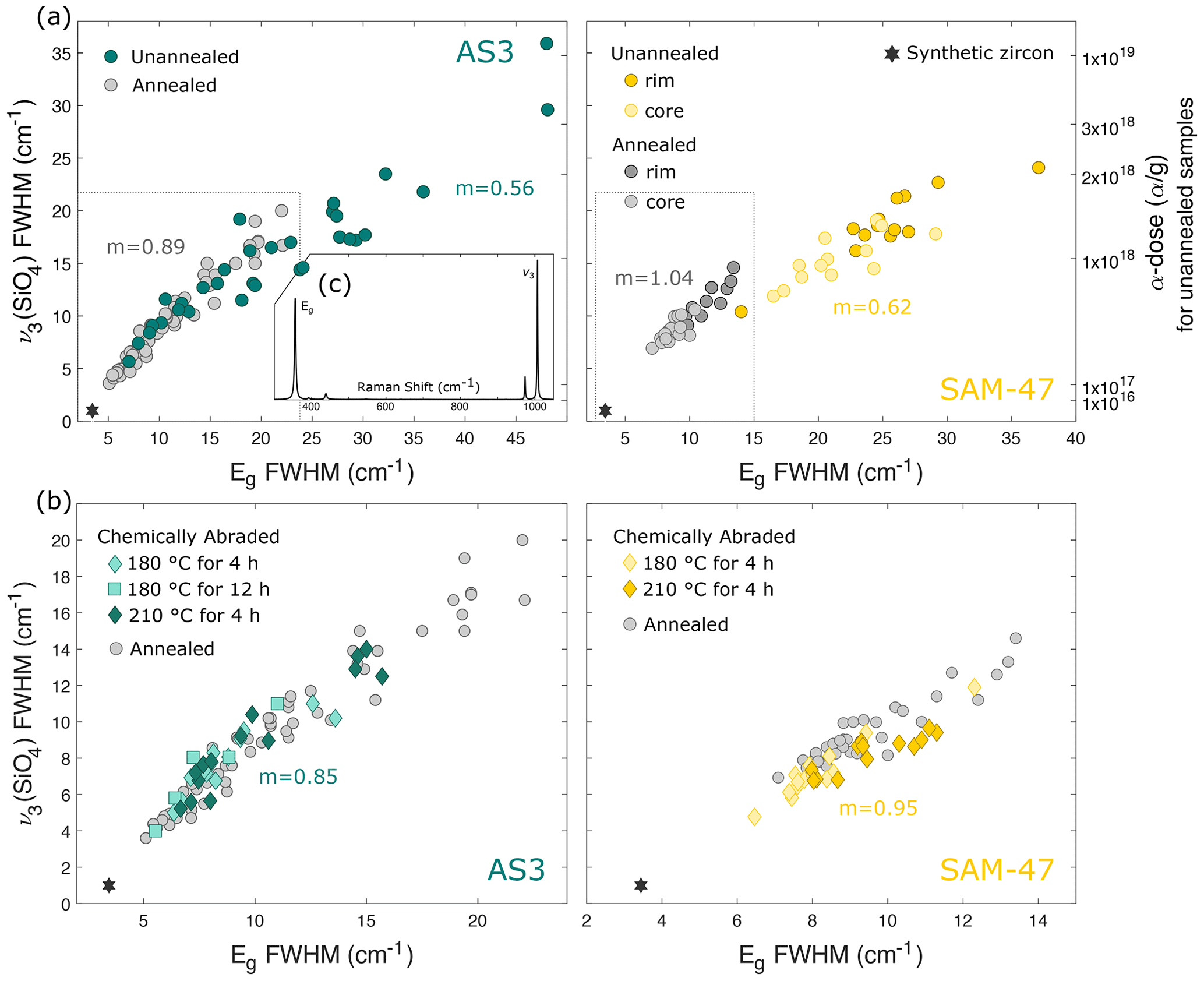
Figure 5Raman v3(SiO4) and Eg peak width data for intermediate- to high-damage samples AS3 and SAM-47. (a) Results for unannealed and annealed (900 ∘C for 48 h) zircon samples. Alpha dose estimates for unannealed zircon samples derived from measured v3(SiO4) peak widths are shown on the right y axis (Váczi and Nasdala, 2017). Slopes (m) for unannealed and annealed samples were calculated assuming a simple linear regression. Gray boxes mark the plot area presented in (b). (b) Results for chemically abraded residues compared to annealed samples. Reported slopes are inclusive of all leaching conditions. (c) Representative spectrum of synthetic zircon with peak assignments.
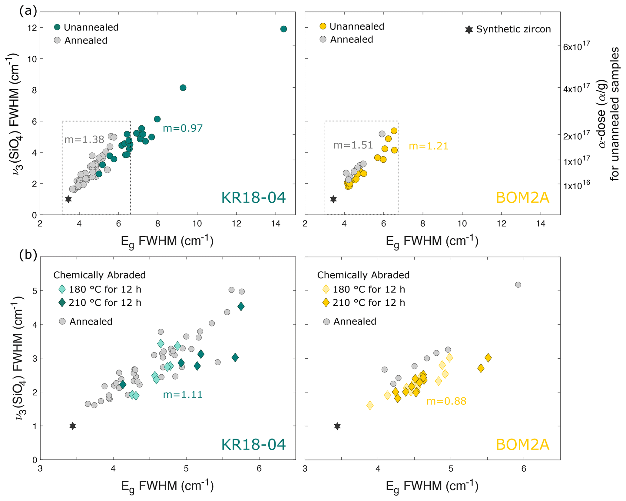
Figure 6Raman v3(SiO4) and Eg peak width data for lower-damage samples KR18-04 and BOM2A. (a) Results for unannealed and annealed (900 ∘C for 48 h) zircon samples. Alpha dose estimates for unannealed zircon samples derived from v3(SiO4) peak width measurements are shown on the right y axis (Váczi and Nasdala, 2017). Slopes (m) for unannealed and annealed samples were calculated assuming a simple linear regression. Gray boxes mark the plot area presented in (b). (b) Results for chemically abraded residues compared to annealed samples. Reported slopes are inclusive of all leaching conditions.
3.1 Images of polished grain mounts
SEM and reflected-light images of annealed AS3 and SAM-47 grains are presented in Fig. 3. CL images of AS3 grains display broad concentric or convoluted zoning patterns with evidence of hydrothermal alteration. Many crystals are finely fractured, and some have large melt inclusions oriented elongate to the c axis. Some fractures and alteration zones cross-cut compositional zones. SAM-47 crystals are not CL-luminescent. Reflected-light images acquired under the Raman microscope, however, reveal fine-scale concentric zoning. BSE images indicate that some crystals are finely fractured and included. Many inclusions are cross-cut by fractures. SEM images of annealed KR18-04 and BOM2A grains are presented in Fig. 4. Both samples exhibit concentric zoning with some faint, broad zones. Fractures are rare. Many BOM2A crystals have needle-like apatite inclusions.
3.2 Raman spectroscopy
3.2.1 Polished grain mounts of unannealed and annealed samples
Key bands in the zircon Raman spectrum – most notably the v3(SiO4) asymmetric SiO4 stretching band near ∼ 1008 cm−1 and the external Eg mode near ∼ 357 cm−1 – broaden and shift to lower frequencies with increasing radiation damage (Nasdala et al., 1995; Zhang et al., 2000; Nasdala et al., 2001; Anderson et al., 2020a; Härtel et al., 2021). Multiple Raman analyses were made on several grains from each sample set to assess intra-crystalline variations in radiation damage. Measured v3(SiO4) and Eg peak widths and positions are reported in Table S1 in the Supplement. Peak width ranges for the v3(SiO4) band for all samples are summarized in Table 2. Equivalent alpha doses (α g−1) for unannealed samples were derived using the relationship between the v3(SiO)4 peak width and equivalent alpha dose for Sri Lankan zircon (Palenik et al., 2003; Váczi and Nasdala, 2017) (Table 1). This relationship – calculated assuming an equivalent damage accumulation interval of 375 Myr to account for the partial annealing of radiation damage in Sri Lankan zircon – nicely fits the dataset of unannealed zircon presented by Nasdala et al. (2001), suggesting that the relationship is broadly appropriate for zircon from a wide range of geological environments.
Table 2Minimum and maximum v3(SiO4) FWHM values for unannealed, annealed, and chemically abraded zircon samples.

Unannealed AS3 and SAM-47 grains have intermediate to high degrees of radiation damage with strong inter- and intra-crystalline variations (Fig. 5a, Table 2). CL-black regions in AS3 samples that yielded anomalous zircon spectra with fluorescent artifacts indicative of altered material were excluded from radiation damage estimates. Rims in SAM-47 samples have accumulated more radiation damage than cores, indicating that rims are enriched in actinides relative to cores. Alpha dose estimates for both AS3 and SAM-47 span above and below the estimated alpha dose threshold assigned to fission-track percolation of 1.9 × 10¹⁸ α g−1 (Ketcham et al., 2013). Importantly, this threshold also corresponds to key transitions in zircon material properties including density (Holland and Gottfried, 1955; Murakami et al., 1991; Ewing et al., 2003). Unannealed KR18-04 and BOM2A zircon samples have low to intermediate levels of radiation damage and a lesser degree of radiation damage zoning (Fig. 6a, Table 2).
Raman peak widths in annealed AS3, SAM-47, and KR18-04 samples are narrower than their unannealed counterparts, indicating partial annealing of radiation damage (Figs. 5a, 6a, and Table 2) (Zhang et al., 2000; Geisler et al., 2001a, b; Ginster et al., 2019; Härtel et al., 2021). Peak width ranges for each sample are also more restricted, implying that annealing has decreased the magnitude of inter- and intra-crystalline variations in radiation damage. Annealing has had a minimal effect on the crystallinity of BOM2A. The most crystalline annealed BOM2A and KR18-04 samples have peak widths that closely approach that of synthetic zircon. The slight differences between the natural and synthetic samples could reflect minor residual radiation damage or slight differences in lattice strain related to zircon composition and other intrinsic defects.
The relationship between the v3(SiO4) and Eg peak widths steepens upon annealing in each of the four samples, since the two Raman peaks have different temperature sensitivities (Härtel et al., 2021). This observation once again confirms that thermal annealing is not the inverse of radiation damage accumulation as demonstrated by previous annealing studies (e.g., Zhang et al., 2000; Geisler et al., 2002; Ginster et al., 2019). As such, we caution against using the Váczi and Nasdala (2017) v3(SiO4)–alpha dose relationship to derive alpha dose estimates for either the annealed or chemically abraded samples.
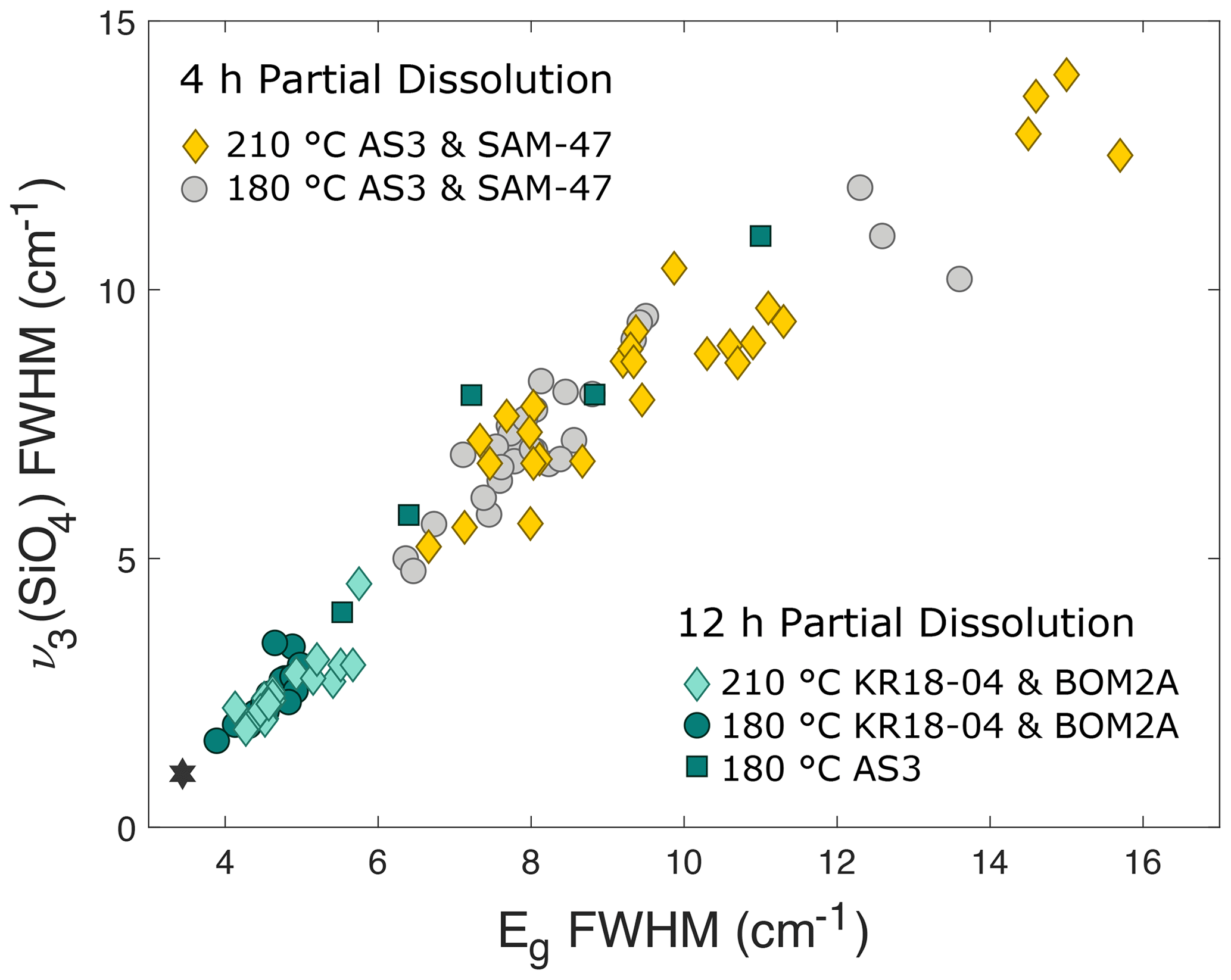
Figure 7Raman v3(SiO4) and Eg peak width results for all chemically abraded zircon residues.
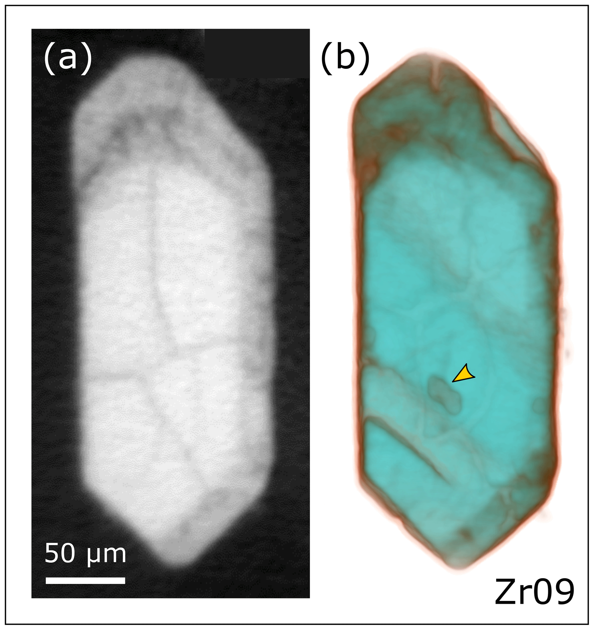
Figure 8µCT images of a zircon with density zoning. (a) A single 2D µCT image slice of an annealed – but not leached – AS3 grain with a dark, low-density damaged rim and a light, high-density crystalline core. (b) Semi-transparent 3D rendering of the µCT image stack for the same grain. High-density zircon is teal, and lower-density material is orange–brown. The arrow marks an interior inclusion. The faint stripes are surface indents of surficial inclusions not shown.
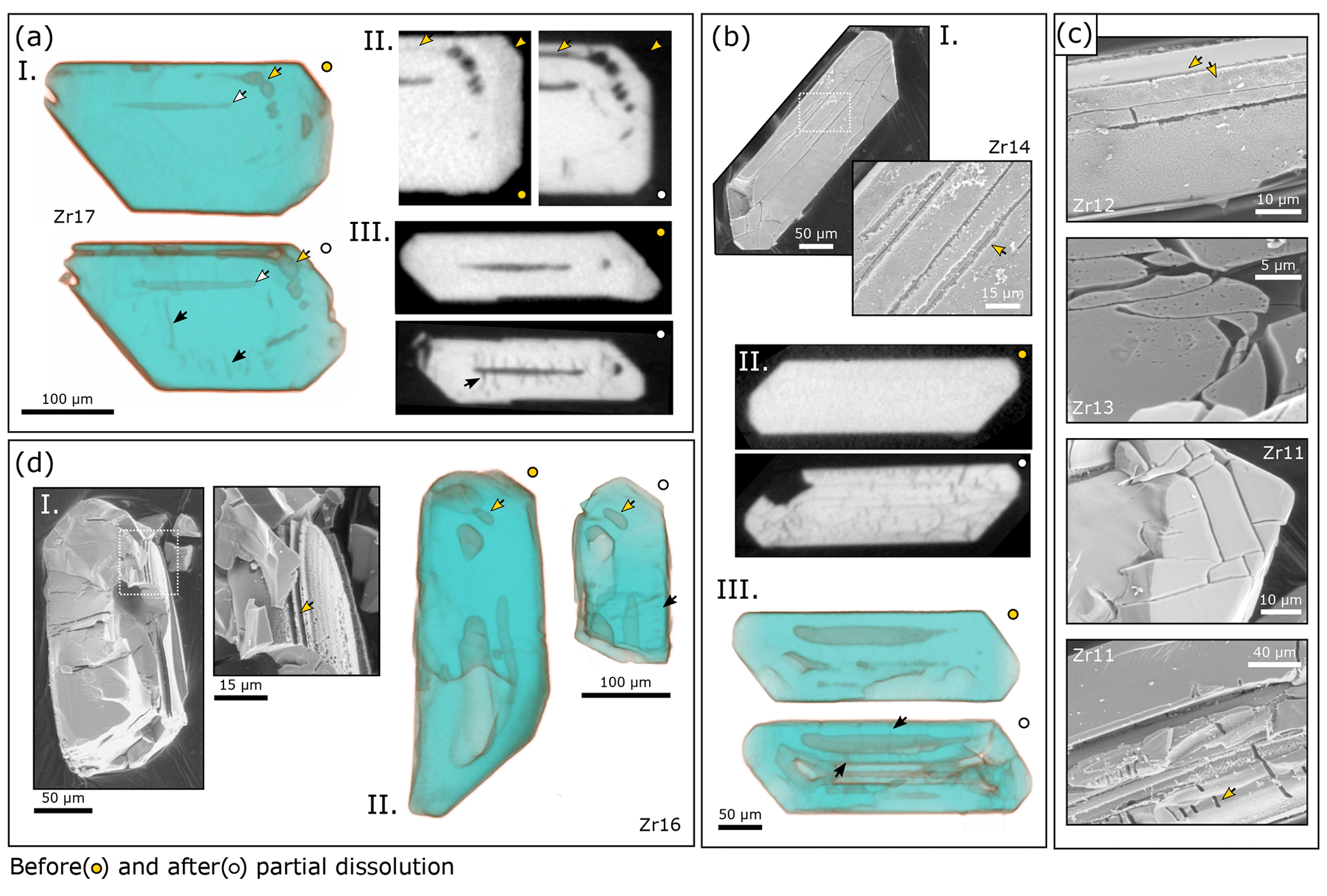
Figure 9SE and µCT images of AS3 grains pre- and post-chemical abrasion (yellow dots and white dots, respectively) at 180 ∘C for 4 h. (a) Subpanel (I) shows semi-transparent 3D renderings of µCT data for Zr17, showing melt inclusions removed by partial dissolution (yellow and white arrows) and newly visible fractures (black arrows). (II) 2D µCT image slices showing the removal of a metamict rim and interior zone. (III) 2D µCT cross section of the melt inclusion marked by white arrows in (I). Newly visible radial fractures have developed along the length of the melt inclusion (black arrow). (b) Subpanel (I) shows SE images of Zr14, showing the widening of fractures on the grain surface. (II) 2D µCT image slices showing a fracture network after partial dissolution. (III) 3D rendering of µCT data showing radial fractures (black arrows) around large melt inclusions removed by partial dissolution. (c) SE images of zircon residues illustrating the contrast between a smooth, low-damage surface and a higher-damage pitted surface (Zr12), curved acid paths, small etch pits (Zr13), blocky fractures (Zr11 top), and dumbbell-like dissolution features (Zr11 bottom). (d) Subpanel (I) shows SE images of Zr16, showing the removal of fine-scale zones. (II) 3D rendering of µCT data showing the removal of large melt inclusions (yellow arrows), the formation of a parallel fracture sequence (black arrow), and significant volume loss, likely due to breakage along the grain center where there are two giant melt inclusions.
3.2.2 Chemically abraded zircon residues
Raman results for chemically abraded residues broken down by zircon sample are shown in Figs. 5b and 6b. The broadest peaks for AS3, SAM-47, KR18-04, and BOM2A residues are narrower than their unleached counterparts, indicating that HF leaching has dissolved the most damaged material in each sample leaving behind a more crystalline zircon residue. Notably, residue data points for SAM-47 and BOM2A samples largely plot below (at lower v3 for a given Eg) the annealed data points. The slope of the v3(SiO4) and Eg relationship is also shallower for all four chemically abraded sample sets when compared to their annealed sample sets. Taken together, these observations could suggest that additional structural changes occur during HF leaching.
In Fig. 7 we compile Raman results for all chemically abraded residues to evaluate how different leaching conditions affect zircon crystallinity. The spread in data points for AS3 residues leached at 180 ∘C for 12 h is shifted toward narrower values compared to AS3 and SAM-47 residues leached at either 180 or 210 ∘C for 4 h, implying that increasing the leaching duration results in a more crystalline zircon residue due to the progressive dissolution of higher-damage domains. Somewhat surprisingly, leaching temperature does not appear to have a significant effect on residue crystallinity; AS3 and SAM-47 samples leached for 4 h at 180 or 210 ∘C have residues with broadly similar peak width distributions, as do KR18-04 and BOM2A samples leached for 12 h at 180 or 210 ∘C. This could reflect a small-n problem. AS3 residues leached at 180 ∘C for 12 h have universally broader peak widths compared to KR18-04 and BOM2A residues treated under the same leaching conditions, highlighting that a sample's initial radiation damage profoundly affects its residue's crystallinity.
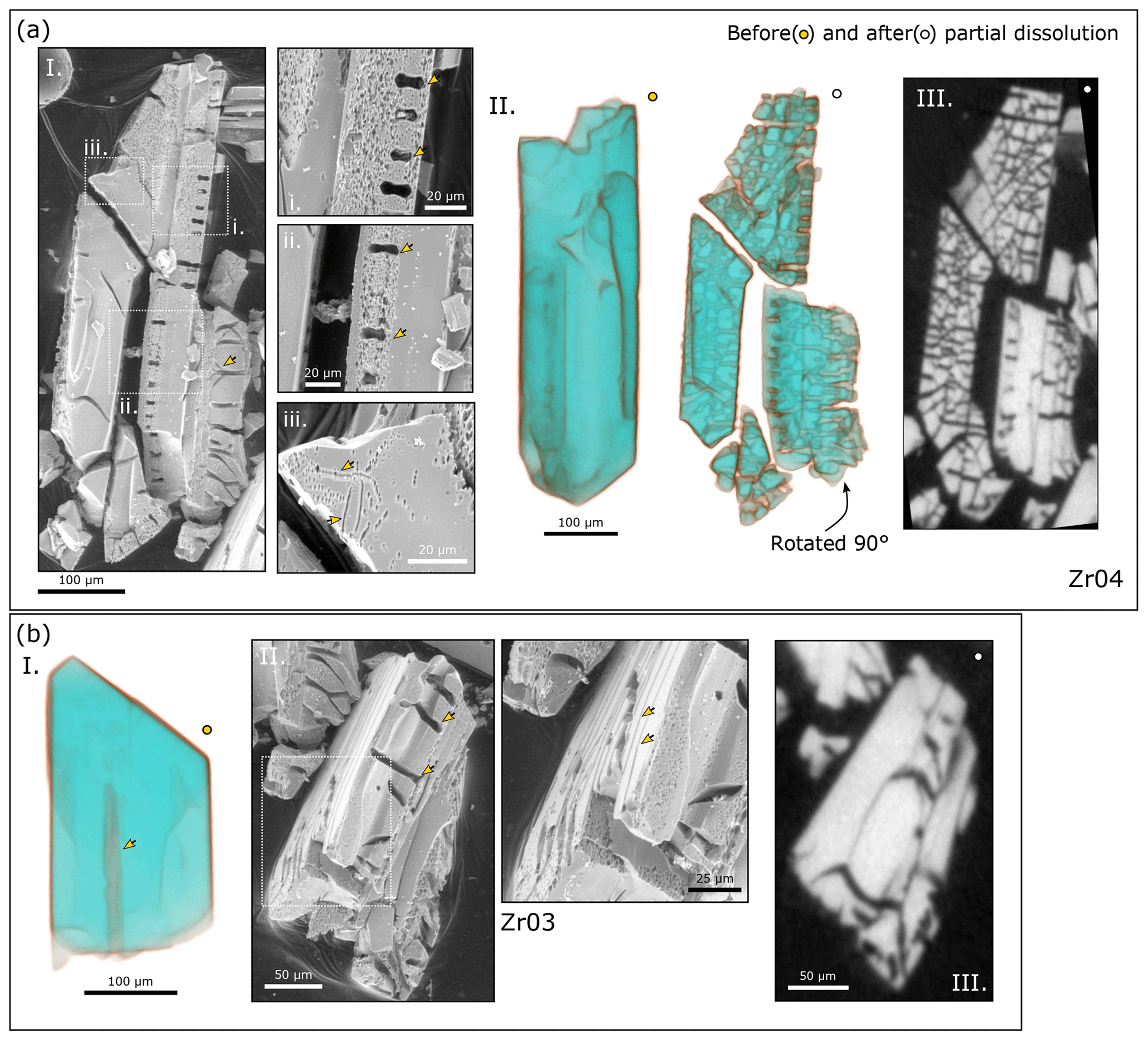
Figure 10SE and µCT images of AS3 grains pre- and post-chemical abrasion at 210 ∘C for 4 h. (a) Subpanel (I) shows SE images of Zr04, a large crystal broken into four pieces. The rotated piece marked with a yellow arrow shows a nice cross section of the grain interior. The arrow highlights an example of a branching channel. The higher-magnification images show that these channels correlate with dumbbell features that cross-cut zones of relatively low (box i) or high (box ii) radiation damage. Box (iii) shows etch pit arrays likely indicative of dislocation loops or low-angle grain boundaries. (II) 3D rendering of the µCT data showing the development of a complex dissolution network in the crystal's interior. (III) 2D µCT image slice showing that the intensive fracturing observed in 3D is restricted to a narrow plane within the crystal. (b) Subpanel (I) shows a semi-transparent 3D rendering of µCT data for Zr03, showing a large melt inclusion. (II) SE images show elongated, channel-like dumbbells (low magnification) and the apparent removal of fine-scale zones (high magnification). (III) 2D µCT image slice showing wide acid paths in the grain interior.
3.3 µCT imaging of radiation damage zoning
The accumulation of radiation damage decreases the density of zircon by 17 % from ∼ 4.7 to 3.9 g cm−3, with the most rapid density change occurring over an alpha dose interval of ∼ 1 × 10¹⁸ to ∼ 4 × 10¹⁸ α g−1 (Holland and Gottfried, 1955; Murakami et al., 1991; Ewing et al., 2003; Nasdala et al., 2004). Raman data for unannealed AS3 and SAM-47 grains indicate that these samples have alpha doses spanning above and below this interval. Lower-density materials attenuate X-rays less, so metamict zircon should appear darker in grayscale µCT image slices than crystalline zircon. Indeed, some AS3 and SAM-47 grains exhibit density zoning (Fig. 8), indicating that annealing at 900 ∘C for 48 h does not significantly increase the density of metamict material. Importantly, µCT does not capture variations in radiation damage below the ∼ 1 × 10¹⁸ α g−1 density change threshold; density zoning is not observed in any of the low- to intermediate-damaged KR18-04 and BOM2A samples.
3.4 Imaging textures before and after partial dissolution
3.4.1 AS3
AS3 residues are white and brittle (Fig. 2b). Most residues treated at 180 ∘C for 12 h and a large fraction of grains treated at 180 or 210 ∘C for 4 h broke apart during rinsing or transfer from the microcap to the tape. SE and µCT images of grains before and after chemical abrasion are presented in Figs. 9, 10, 11, S1, and S2. Each figure shows results for one of the three leaching conditions – 180 ∘C for 4 h, 210 ∘C for 4 h, and 180 ∘C for 12 h. Here we briefly summarize key observations. We refer the reader to the figure captions for additional context.

Figure 11SE and µCT images of AS3 pre- and post-chemical abrasion at 180 ∘C for 12 h. (a) Subpanel (I) shows SE images of sample Zr27, showing a row of dumbbells along the length of the zircon crystal. The higher-magnification SE image shows a sponge-like surface texture. (II) A series of 2D µCT image slices progressively stepping down to view structures beneath the crystal's surface. The yellow arrows highlight the same dumbbell features marked on the SE image in (I). The teal arrows highlight fractures, many of which radiate from dumbbell features. The white arrows mark another series of dumbbells on the bottom side of the crystal. (III) Cross-sectional 2D µCT image slices of a–a′ and b–b′ as labeled in (II). White arrows mark a second set of dumbbells with a different crystallographic orientation. (IV) Semi-transparent 3D rendering of µCT data with arrows highlighting a large melt inclusion. The dissolution of this inclusion likely caused the grain to break into two pieces. The white arrows mark the same row of dumbbells as indicated by the white arrows in (II). (b) Subpanel (I) shows a semi-transparent 3D rendering of µCT data for Zr28. (II) SE image of the husk-like zircon shell with large dumbbell features. (c) SE images of zircon residues Zr26, Zr32, and Zr23 showing cobblestone-, straw-, and lace-like textures.
Damaged zircon is more soluble in HF than crystalline zircon. µCT images show that low-density, high-damage rims and interior zones dissolved early and at low temperatures (180 ∘C for 4 h). SE images also document the removal of fine zones early in the leaching process. Etching in SE images reflects the removal of soluble defects such as partially annealed radiation damage, dislocations, low-angle grain boundaries, and intrinsic point defects. Low-damage zones have smooth surfaces, whereas higher-damage zones have pitted or sponge-like surfaces due to etching of closely spaced, radiation-related defects in SE images (Figs. 9c and 10a.I). For spatial reference, fission tracks are ∼ 16.7 µm and alpha recoil tracks (clusters of alpha recoil tracks stemming from a single decay chain) average ∼ 125 nm in length prior to annealing or etching (Ewing et al., 2003; Jonckheere, 2003). Etch pits are not observed in µCT images due to the dataset's lower spatial resolution.
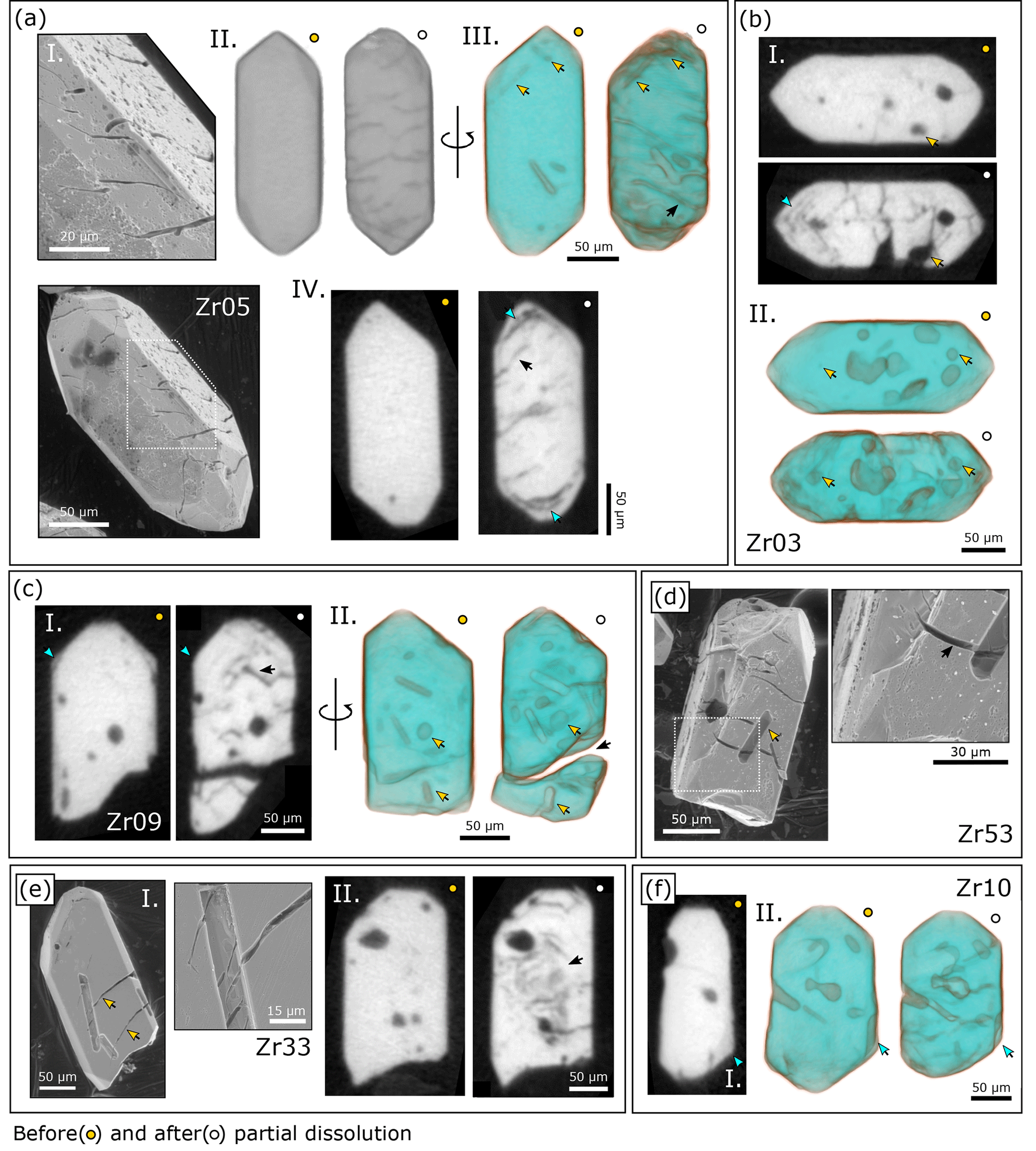
Figure 12SE and µCT images of SAM-47 grains pre- and post-chemical abrasion at 180 ∘C for 4 h. (a) Subpanel (I) shows SE images of Zr05, showing deep grooves on the grain's surface and a sponge-like etch texture. (II) Opaque 3D rendering of µCT data showing that these surface fractures are only apparent after partial dissolution. (III) Semi-transparent 3D rendering of µCT data with yellow arrows marking inclusions removed by partial dissolution. (IV) 2D µCT image slices highlighting an example of an acid path into the grain interior (black arrow) and the removal of concentric zones (teal arrow). (b) Subpanel (I) shows 2D µCT image slices showing the removal of fine-scale concentric zones (teal arrow) and a mineral inclusion (yellow arrows) in Zr03. (II) Semi-transparent 3D rendering of µCT data with yellow arrows depicting the removal of more mineral inclusions. (c) Subpanel (I) shows 2D µCT image slices of Zr09, showing the removal of a low-density rim (teal arrow) and an acid path into the grain interior (black arrow). (II) Semi-transparent 3D rendering of µCT data highlighting the removal of inclusions (yellow arrows) and the formation of a large fracture (black arrow). (d) SE images of Zr53 showing crystal-shaped voids interpreted as dissolved surface-reaching inclusions (yellow arrow) and the fractures that cross-cut these voids (black arrow). (e) SE images of Zr33, again showing fractures cross-cutting inclusions removed by partial dissolution (yellow arrows) and a smooth grain surface. (II) 2D µCT image slices showing a convolute pattern of material dissolved from the crystal core. (f) Subpanel (I) shows 2D µCT image slices highlighting a low-density rim on Zr10. (II) Semi-transparent 3D rendering of µCT data showing the removal of this rim.
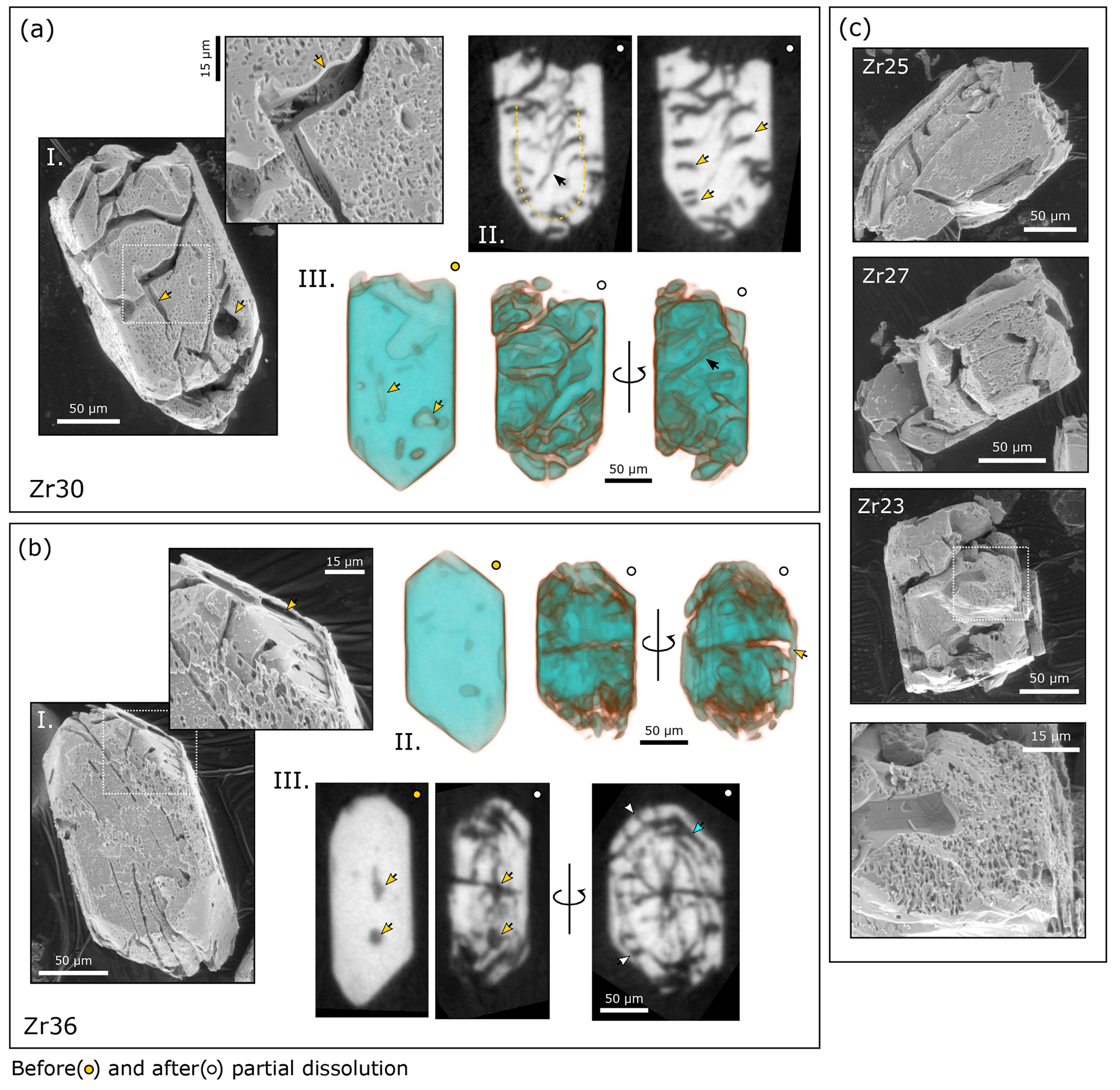
Figure 13SE and µCT images of SAM-47 grains pre- and post-chemical abrasion at 210 ∘C for 4 h. (a) Subpanel (I) shows SE images of Zr30, showing wide fractures, the removal of mineral inclusions (yellow arrows), and a moderately etched surface. (II) 2D µCT image slices highlighting dumbbell-like features (yellow arrows) interpreted to cross-cut what could be a concentric zone (yellow dashed line). The black arrow exhibits how fractures radiate from the dumbbell features. (III) Semi-transparent 3D rendering of µCT data. Yellow arrows correlate with those in (I). The black arrow highlights how the fractures observed on the surface propagate through the crystal interior. (b) Subpanel (I) shows SE images of Zr36, showing fractures, diamond-shaped etch pits, and the targeted removal of an interior zone (yellow arrow). (II) Semi-transparent 3D rendering of µCT data. The yellow arrow highlights the grain's shell-like appearance because of significant dissolution in the grain's interior. (III) 2D µCT image slices showing the removal of mineral inclusions (yellow arrows), oscillatory zones (teal arrow), and dumbbell-like fractures that appear to cross-cut compositional zones (white arrows). (c) SE images of dog-chewed zircon residues Zr25, Zr27, and Zr25.
The shape of etch pits is independent of the nature of the defect (Jonckheere and Van den Haute, 1996; Jonckheere et al., 2005, 2022). A pit's surface symmetry instead reflects crystallographically controlled dissolution, and etch pit geometries vary with crystallographic orientation (Gleadow et al., 1976; Yamada et al., 1995). As such, while individual diamond-shaped etch pits resemble SE images of etched fission tracks presented by others for zircon and other minerals (e.g., Jones et al., 2022), these likely reflect other defect types such as lattice dislocations. Fission tracks are expected to anneal during the pre-leach 900 ∘C heating step (e.g., Yamada et al., 1995, 2007), although some pits could reflect fission tracks that were pre-etched geologically. Given the limited abundance, spacing, and larger size of many diamond- and pyramid-like etch pits, we find them unlikely to represent alpha recoil tracks. Etch pit arrays that do not correlate with expected zoning patterns (Fig. 10a.I, box iii) are interpreted as dislocation loops or low-angle grain boundaries.
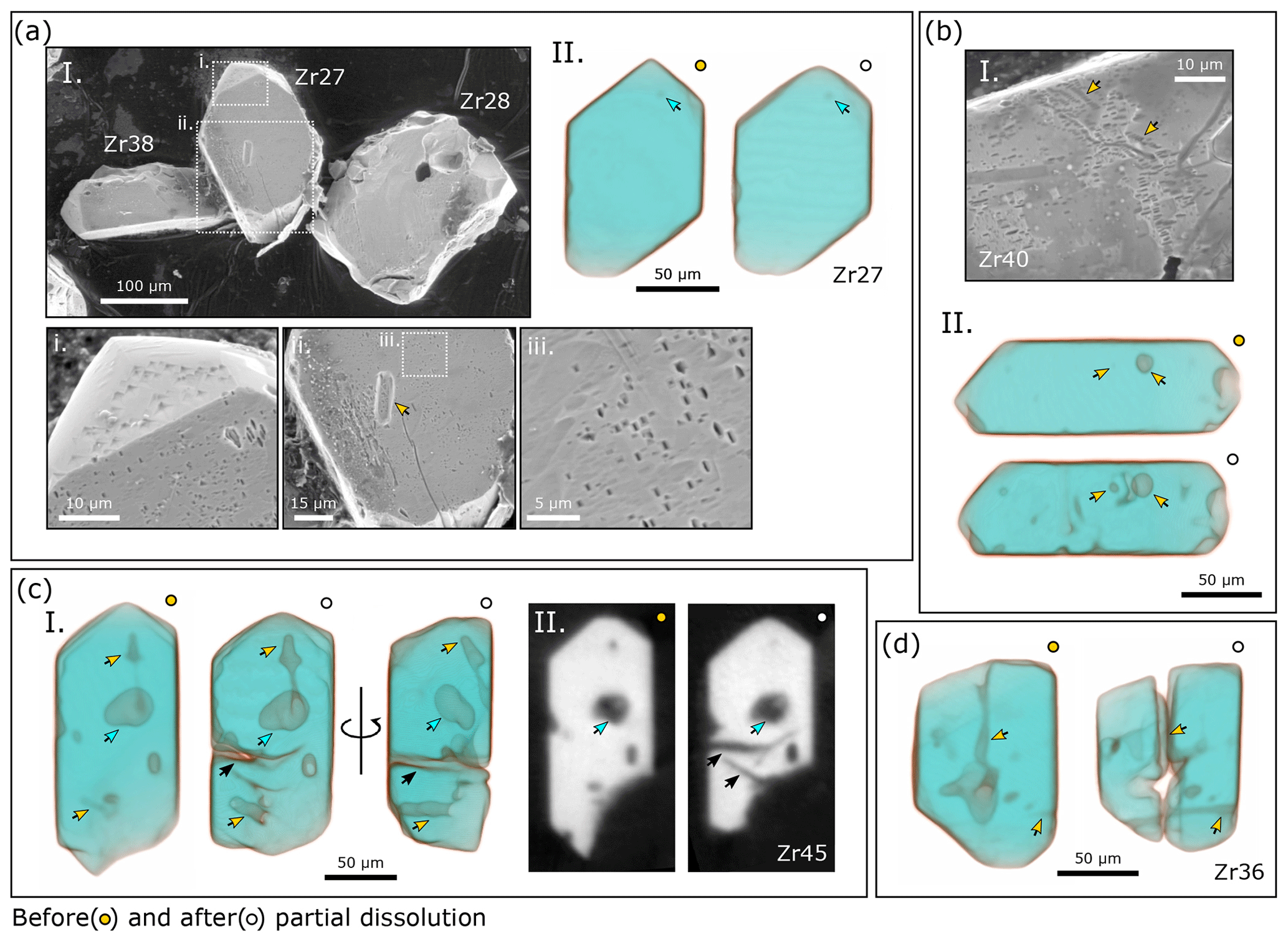
Figure 14SE and µCT images of KR18-04 grains pre- and post-chemical abrasion at 180 ∘C for 12 h. (a) Subpanel (I) shows a low-magnification SE image of zircon samples Zr38, Zr27, and Zr28 and higher-magnification images of Zr27, showing close-up images of rectangular and triangular etch pits and the removal of a surface-reaching inclusion (yellow arrow). (II) Semi-transparent 3D rendering of µCT data for Zr27. Arrows highlight an inclusion inferred to have survived partial dissolution. (b) Subpanel (I) shows an SE image of Zr40 with linear etch pit arrays likely indicative of dislocations. (II) Semi-transparent 3D rendering of µCT data highlighting inclusions that dissolved. (c) Subpanel (I) shows a semi-transparent 3D rendering of µCT data for Zr45. Teal arrows highlight a large inclusion inferred to have survived partial dissolution, while yellow arrows mark inclusions that dissolved. Black arrows mark acid paths. (II) 2D µCT image slices. Teal arrows mark the same multi-phase inclusion in (I). Black arrows mark acid paths not apparent in the before imagery dataset. (d) Semi-transparent 3D rendering of µCT data for Zr36. Yellow arrows highlight surface-reaching inclusions removed by partial dissolution, resulting in a large cavity in the grain's interior.
Etch textures are subtle at low temperatures and short leaching durations. At hotter temperatures and longer leaching durations, etched zones have deeper, sponge-like textures indicative of a greater degree of dissolution. When leached at 180 ∘C for 12 h, only a heavily dissected crystalline husk, a collection of perforated straw-like zones, or a cobblestone-like residue is sometimes all that remains.
Other interesting textures in AS3 residues include geometrical dissolution features that cross-cut radiation damage zones as highlighted in Figs. 10a and 11a, which we refer to as dumbbells. Some dumbbells cross-cut zones of relatively high damage, while others cross-cut zones of relatively low damage. Dumbbells are oriented normal to the crystal (the c axis). 3D rendering of µCT data reveals that dumbbells are surface expressions of complex fracture networks that are spatially restricted to specific zones. The geometrical shape of dumbbells and the wide, branching, and channel-like appearance of some fractures in SE imaging indicate that these fracture networks are focal points for crystallographically controlled dissolution.
Our µCT dataset also generates new insights into the fate of inclusions. In µCT image slices of unleached grains, inclusions appear dark with grayscale intensities marginally above that of background (air and tape) due to their low density and mean atomic number relative to that of zircon. We interpret an inclusion to have dissolved if its grayscale intensity decreases to that of background, if its size or morphology changes after leaching, or if an acid path leads to the inclusion. We find that inclusions dissolved under each leaching condition investigated. Radial fractures are commonly present around dissolved inclusions in residues (Fig. 9b.I).
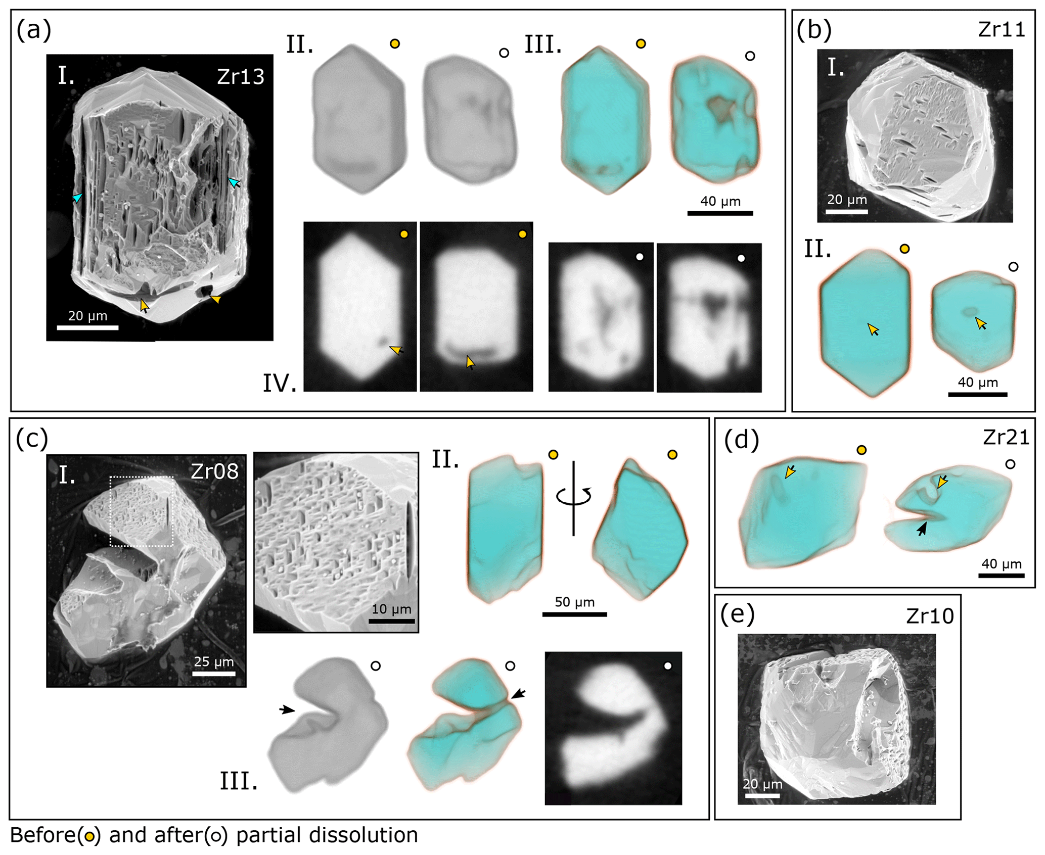
Figure 15SE and µCT images of KR18-04 grains pre- and post-chemical abrasion at 210 ∘C for 12 h. (a) Subpanel (I) shows an SE image of Zr13, showing dissolved inclusions (yellow arrows) and the removal of oscillatory zones (teal arrows). (II) Opaque 3D rendering of µCT data. (III) Semi-transparent 3D rendering of µCT data. (IV) Representative 2D µCT image slices indicating that a significant amount of zircon material was dissolved from the grain's interior. Yellow arrows correlate with those in (I). (b) Subpanel (I) shows an SE image of Zr11, showing deep etch pits on (100) with the long axes oriented parallel to the crystal's c axis. Etch pits are absent from other crystal faces. (II) Semi-transparent 3D rendering of µCT data showing a dissolved inclusion. (c) Subpanel (I) shows SE images of Zr08. The high-magnification image shows closely spaced and overlapping prismatic etch pits that form a sponge-like texture. (II) Semi-transparent 3D rendering of µCT data acquired before partial dissolution. (III) Opaque and Semi-transparent µCT 3D renderings and a representative 2D µ CT image slice of the sample after partial dissolution. Black arrows highlight acid paths into the grain interior. (d) Semi-transparent 3D rendering of µCT data for Zr21. Yellow arrows mark an inclusion that dissolved. The black arrow highlights the acid path that inexplicably cut into the grain interior. (e) SE image of Zr10 with deep prismatic etch pits present on some grain surfaces but not others.
3.4.2 SAM-47
Like AS3 residues, SAM-47 residues are white and brittle (Fig. 2b). Many residues broke during sample transfer, especially those leached at 210 ∘C. SE and µCT images of SAM-47 grains before and after chemical abrasion at 180 ∘C or 210 ∘C for 4 h are presented in Figs. 12, 13, S3, and S4. Some SAM-47 grains have density zoning with dark, high-damage rims and light, crystalline cores. One crystal exhibits concentric density zoning in the grain interior. Like for AS3, these low-density zones dissolve at low leaching temperatures and durations (180 ∘C, 4 h).
SE images of SAM-47 residues treated at 180 ∘C for 4 h show a range of surface textures (Fig. 12). Some grains have smooth, unetched surfaces, while others are more strongly etched, indicating inter- and intra-crystalline variations in radiation damage. Low-intensity chemical abrasion removes surface-reaching inclusions as evidenced by large prismatic voids on grain surfaces. Most of these voids are cross-cut by fractures. Other grains have finer sinuous fracture patterns not associated with inclusions. µCT images show that acid has reached the interior of most zircon residues treated at 180 ∘C for 4 h as well as dissolved inclusions and fine-scale concentric and convolute zones from crystal interiors.
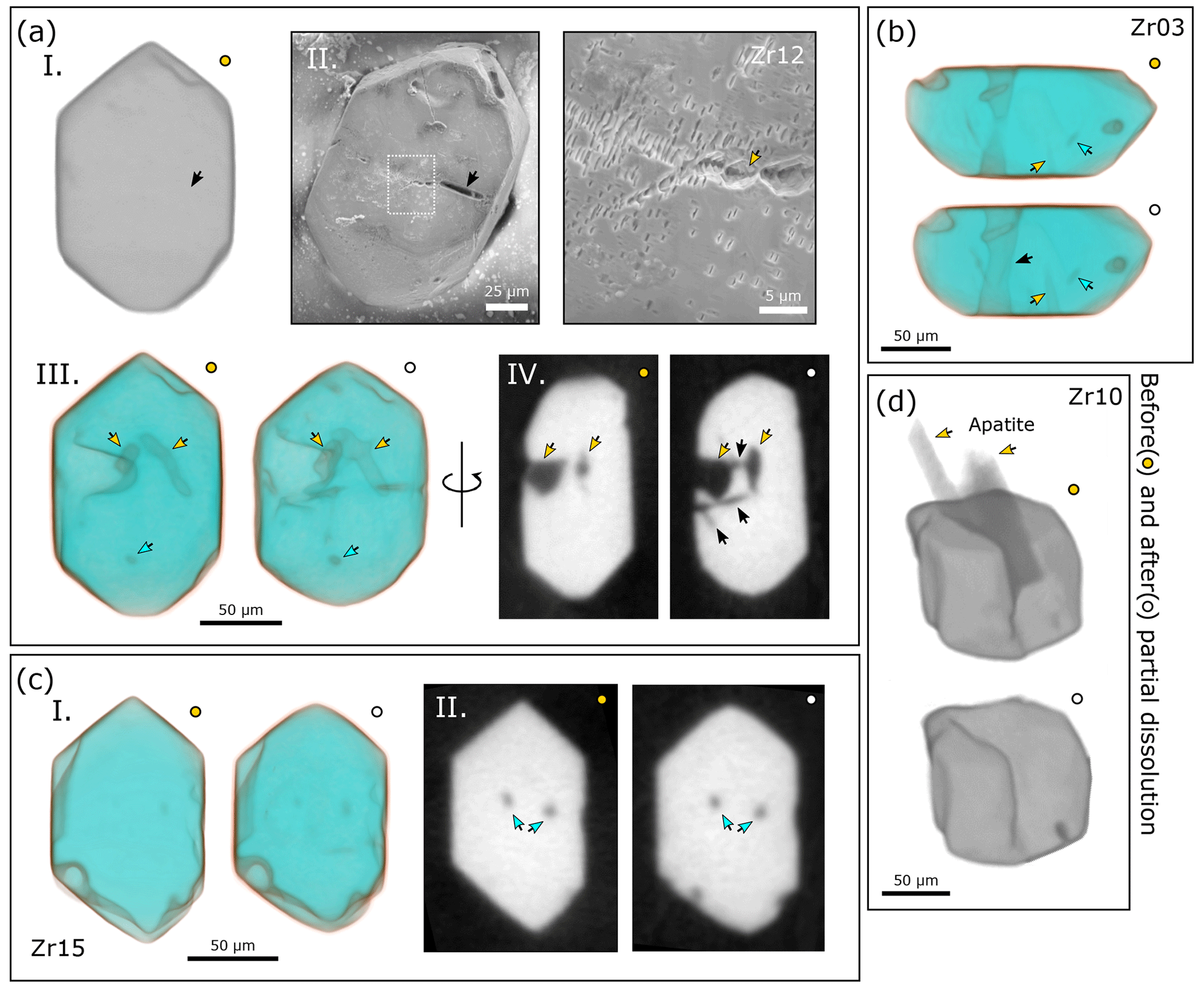
Figure 16SE and µCT images of BOM2A grains pre- and post-chemical abrasion at 180 ∘C for 12 h. (a) Subpanel (I) shows an opaque 3D rendering of µCT data for Zr12. (II) SE image of a grain surface with a close-up image of clustered and isolated rectangular etch pits. The black arrow points to a void in the crystal, perhaps related to a surficial inclusion not apparent in the pre-chemical abrasion dataset, and the yellow arrow highlights another interesting dissolution feature. (III) Semi-transparent 3D rendering of µCT data showing inclusions removed by partial dissolution (yellow arrows) and inclusions inferred to have survived (teal arrows). (IV) 2D µCT image slices with yellow arrows depicting inclusions dissolved during chemical abrasion and black arrows highlighting acid paths. (b) Semi-transparent 3D rendering of µCT data for Zr03, showing inclusions removed by partial dissolution (yellow arrows) and inclusions inferred to have survived (teal arrows). The black arrow highlights an acid path cutting through the crystal interior. (c) Subpanel (I) shows a semi-transparent 3D rendering of µCT data for Zr15, suggesting a slight shortening along the c axis. (II) 2D µCT image slices showing inclusions inferred to have survived partial dissolution. (d) Opaque 3D rendering of µCT data for Zr10 showing the removal of large, protruding apatite inclusions by partial dissolution.
SE images of SAM-47 residues treated at 210 ∘C for 4 h are more strongly etched with deep sponge-like textures (Fig. 13). Etch pits are larger with diamond-like shapes similar to those observed in AS3 crystals treated at either 210 ∘C for 4 h or 180 ∘C for 12 h, and fractures are wider. SE images indicate the dissolution of surface-reaching inclusions, and the shell-like appearance of some residues hints at the removal of interior zones. µCT images of residues treated at 210 ∘C for 4 h reveal that concentric zones and inclusions have been dissolved from crystal cores. Acid paths are wider and more interconnected, and fractures cross-cut dissolved mineral inclusions. We observe fracture patterns similar to the dumbbell features in AS3. Drawing a line normal to dumbbell features in a µCT image slice of Zr30 forms a continuous concentric zone (Fig. 13a.II). Other fractures radiate from the dumbbell features. In sample Zr36 (Fig. 13b.III) dumbbell features connect dissolved concentric zones to both one another and the grain surface in a scaffold-like pattern.
3.4.3 KR18-04
KR18-04 residues are transparent and colorless (Fig. 2b). Most residues remained intact during rinsing and transfer. Only grains with large, pre-existing fractures broke apart. µCT and SE images of KR18-04 grains before after chemical abrasion at 180 or 210 ∘C for 12 h are presented in Figs. 14 and 15, respectively. SE images of residues treated at 180 ∘C show intact grains with mildly etched surfaces (Fig. 14). Etch pits on (100) are small, prismatic, and generally rectangular, while etch pits on other crystal faces are more triangular, again highlighting that the shape of etch pits is crystallographically controlled. Linear etch pit arrays are indicative of dislocation loops.
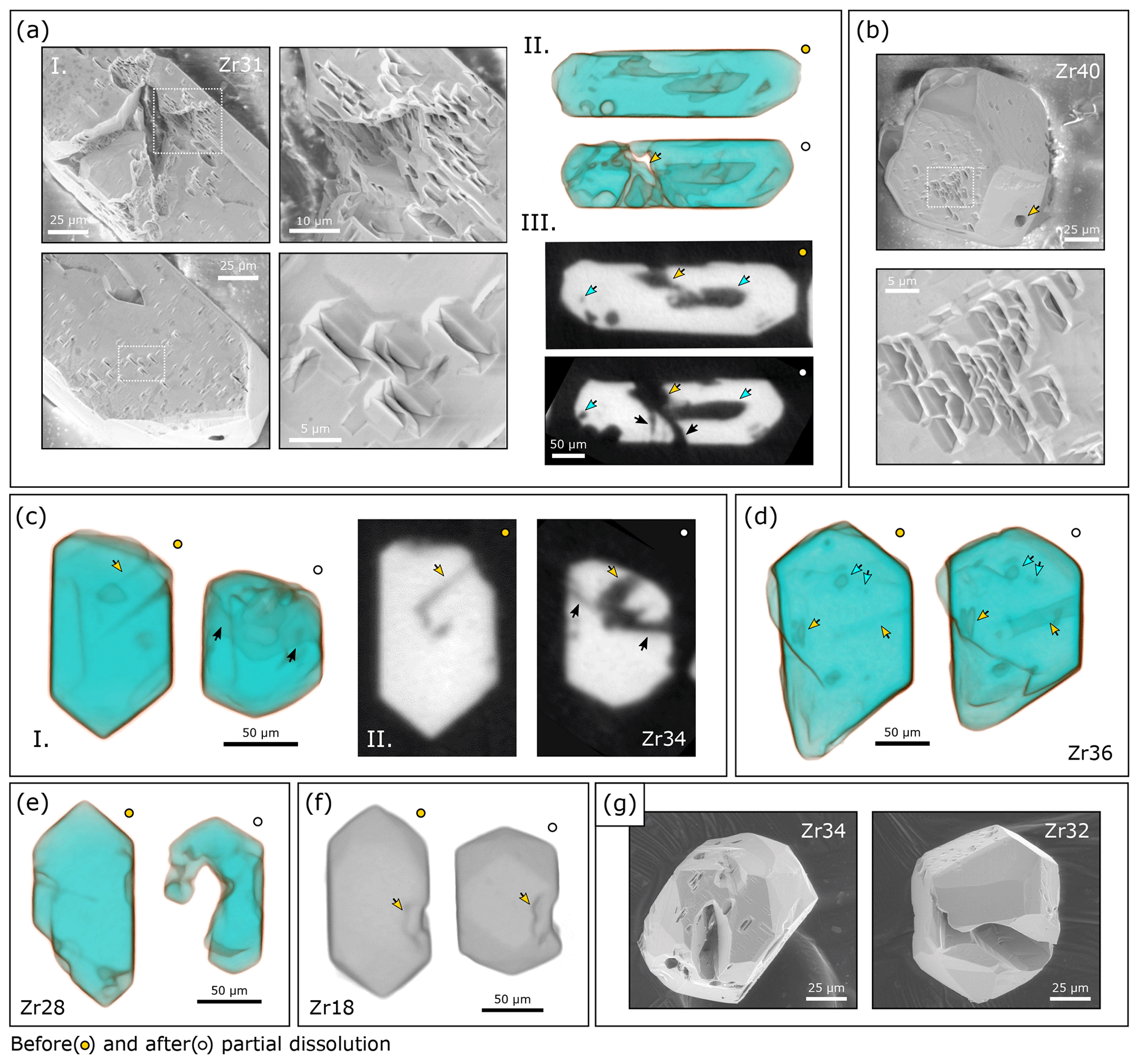
Figure 17SE and µCT images of BOM2A grains pre- and post-chemical abrasion at 210 ∘C for 12 h. (a) Subpanel (I) shows SE images of Zr31, showing deep fractures penetrating the grain's interior. Close-up images showing well-faceted etch pits on (100), some of which are isolated, while others are interconnected. The long axes of deep, octahedral etch pits are oriented parallel to the c axis, whereas the long axes of shallower etch pits are oriented parallel to the a axis. (II) Semi-transparent 3D rendering of µCT data again highlighting the development of large fractures. (III) 2D µCT image slices. Teal arrows highlight inclusions that were dissolved; the yellow arrow points to a surface-reaching inclusion that acted as an acid path into the grain interior, and the black arrow highlights acid paths not observed in the before imagery dataset. (b) SE images of Zr40 that demonstrate how some crystallographic faces are strongly etched, while others are pristine. Etch pits are again strongly prismatic and sometimes interconnected. The yellow arrow points to a void where there was once an inclusion. (c) Subpanel (I) shows a semi-transparent 3D rendering of µCT data for Zr34, showing a significant shortening of the crystal's c axis. (II) 2D µCT image slices. The yellow arrows highlight surface-reaching inclusions removed by partial dissolution. Black arrows mark acid paths not apparent in the before imagery dataset. (d) Semi-transparent 3D rendering of µCT data for Zr36. Teal arrows highlight inclusions inferred to have survived partial dissolution. Yellow arrows highlight inclusions that were dissolved. (e) Semi-transparent 3D rendering of µCT data for Zr28, showing significant volume loss from the grain interior. (f) Opaque 3D rendering of µCT data for Zr18. Yellow arrows highlight how some topographic features are preserved during partial dissolution despite significant volume loss. Note how crystal facets are better developed after partial dissolution. (g) Low-magnification SE images of Zr34 and Zr32 showcasing the crystallographic dependence of surface etching and acid paths that cut deep into grain interiors.
Large crystal-shaped voids on grain surfaces once again indicate that leaching dissolves surface-reaching inclusions. µCT images of residues treated at 180 ∘C suggest that leaching dissolves some – but not all – mineral inclusions from crystal interiors. For example, the large multi-phase inclusion in Fig. 14c.I is interpreted to have survived partial dissolution since (1) there is apparent change to the grayscale intensities of either phase relative to that of background, (2) there is no apparent change to the inclusion's size or morphology, and (3) there is no evidence that an acid path has reached the inclusion. Beam-hardening effects (the halo-like effect around high-density zircon) make it challenging to determine whether or not smaller inclusions survive chemical abrasion. In such cases, grayscale intensity values cannot be used to identify whether or not an inclusion dissolved. Some residues treated at 180 ∘C have fractures or acid paths that lack obvious precursors in the before imagery dataset. Qualitatively, before and after µCT imagery suggests minimal volume loss and a slight shortening of a prismatic grain's c to a aspect ratio.
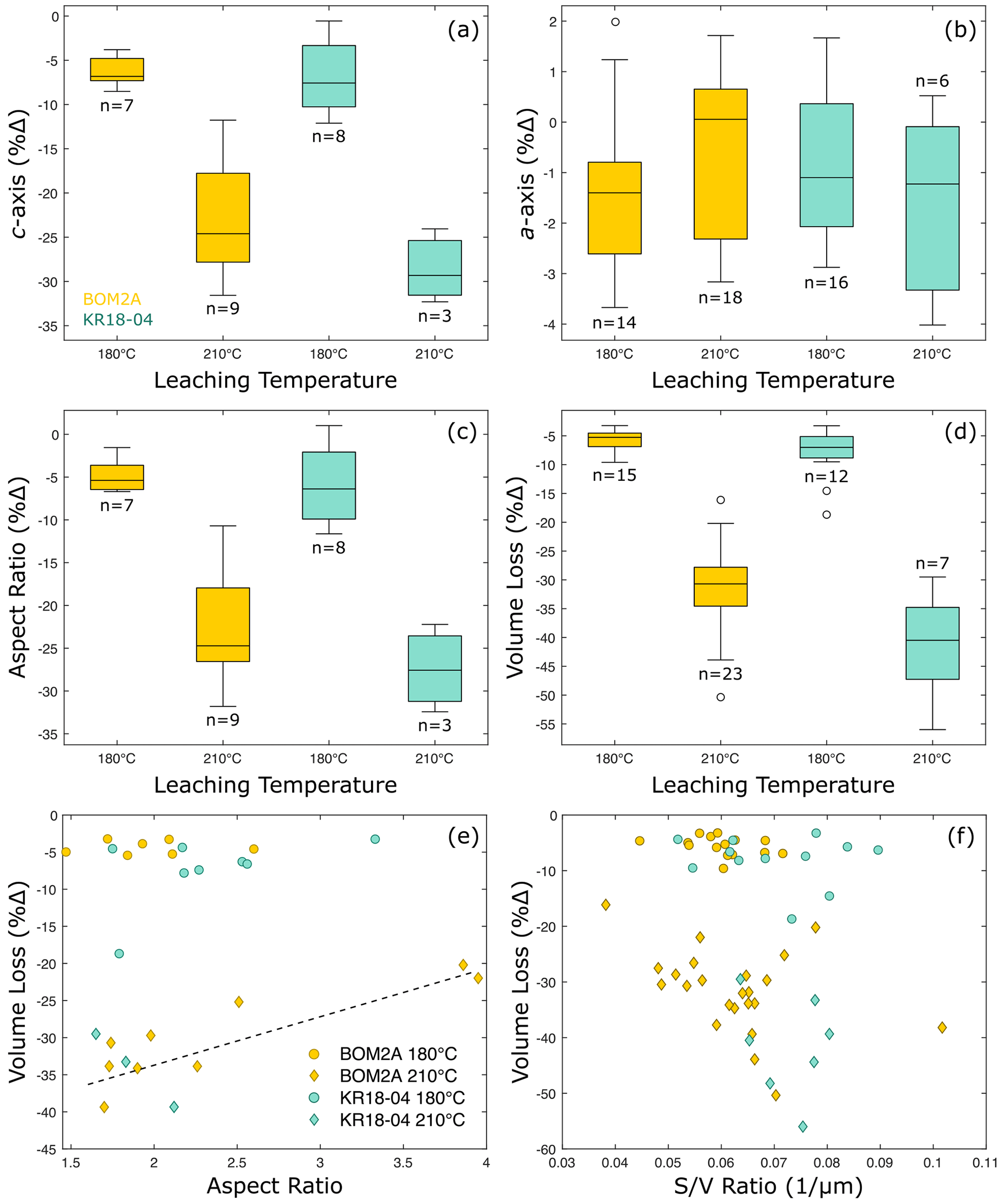
Figure 18Data plots summarizing crystal morphology, volume, and surface area measurements for KR18-04 and BOM2A. (a) Box plot showing how the length of a grain's c axis changes during chemical abrasion. In all box plots, the central line represents the dataset's median; the box extends to the dataset's 25th and 75th percentiles, the whiskers extend to include the full data range excluding outliers, and circle markers are outliers that exceed the 99 % confidence interval. (b) Box plot showing how the length of a grain's a axis changes during chemical abrasion. (c) Box plot showing how a grain's aspect ratio () changes during chemical abrasion. (d) Box plot showing estimated volume loss during chemical abrasion. (e) Scatter plot showing the relationship between a grain's initial aspect ratio and estimated volume loss. (f) Scatter plot showing the relationship between a grain's initial surface-to-volume ratio and estimated volume loss.
SE images of residues treated at 210 ∘C show the removal of fine concentric zones and surface-reaching inclusions. Etch pits are well-preserved on some crystal faces including (100) and entirely absent on others. Etch pits are generally larger than those observed in 180 ∘C residues. Many are deep, rectangular, and well-faceted. The long axes of deep rectangular pits align parallel to the crystallographic c axis, while the long axes of shallower rectangular pits align parallel to the a axis. Etch pit clusters have a sponge-like texture. µCT images of residues treated at 210 ∘C show that acid has dissolved inclusions and zircon material from grain interiors. Some grains have deep carve-outs from crystal interiors with no obvious structural precursor in the before imagery dataset. Before and after imagery suggests higher volume loss and a more pronounced shortening of some grains' aspect ratios.
3.4.4 BOM2A
BOM2A residues are transparent and colorless (Fig. 2b). All residues remained intact during rinsing and transfer. SE and µCT images of BOM2A grains before and after chemical abrasion at 180 or 210 ∘C for 12 h are presented in Figs. 16 and 17, respectively. Etch pits are small and rectangular in SE images of residues treated at 180 ∘C (Fig. 16). Some etch pits are isolated, while others are interconnected. Some surfaces have deep voids that penetrate the grain interior but do not correlate with inclusions. µCT images qualitatively suggest minor volume loss with a slight shortening of the crystal's c axis. Chemical abrasion dissolves surface-reaching inclusions and some – but not all – inclusions from crystal interiors. Some residues have fractures that are spatially associated with inclusions.
SE images of residues treated at 210 ∘C show that etch pits are preserved on some crystal faces but not others, suggesting a crystallographic control on either etch pit formation or preservation (Fig. 17). Like KR18-04 residues leached under the same conditions, etch pits are larger with well-developed facets at hotter leaching conditions. Some etch pits are isolated, while others interconnect to form acid paths into grain interiors. The long axes of deep, prismatic etch pits on (100) align with the crystal's c axis, while the long axes of shallower etch pits align with the crystal's a axis. Some SE images show that acid has penetrated deeply into grain interiors, forming what look like caverns. Many of these caverns lack obvious precursors in the before imagery dataset. µCT images show that the dissolution of surface-reaching inclusions allows acid into crystal cores. Fractures in SE images are sometimes associated with large mineral inclusions. Like the 180 ∘C leach, we find that leaching at 210 ∘C dissolves some – but not all – interior inclusions. Qualitatively, volume loss appears greater at 210 ∘C, and the c axis is considerably shorter in most crystals after partial dissolution. Before and after images show that some surface topographic features are preserved during chemical abrasion. Some residues are more strongly faceted than they were prior to chemical abrasion.
3.5 Quantifying volume loss and changes to crystal morphology
All quantitative measurements made using the ruler and segmentation functions in Dragonfly ORS software for samples KR18-04 and BOM2A are presented in Tables S2 and S3 and summarized in Fig. 18. Leaching at 180 ∘C for 12 h causes a ∼ 5 % to 10 % decrease in the length of a crystal's c axis (Fig. 18a). Increasing the leaching temperature to 210 ∘C results in a greater degree of shortening on the order of ∼ 15 % to 30 %. In contrast, the length of a crystal's a axes shows little (maximum <4 %) to no change after leaching at 180 or 210 ∘C (Fig. 18b). Consequently, the aspect ratio () of a crystal decreases during chemical abrasion (Fig. 18c). A 2 % change in a crystal with an initial axis length of 80 µm equates to a change of 1.6 µm, which is approximately the spatial resolution of our µCT dataset (1.62 µm). As such, we take ∼ 2 % to be a minimum estimate for our measurement error.
Estimated volume losses are presented in Fig. 18d. Fine-scale dissolution features and small mineral inclusions are sometimes missed by the grayscale segmentation method used due to a combination of beam-hardening effects, which manifest as bright halos around zircon edges, and the relatively low spatial resolution of the µCT dataset. As such, volume loss estimations are considered first-order approximations for minimum volume loss. We find that chemical abrasion at 180 ∘C for 12 h dissolves ∼ 5 % to 10 % of a grain by volume, whereas chemical abrasion at 210 ∘C for 12 h dissolves ∼ 25 % to 50 % of a grain by volume. Although there is considerable overlap between the BOM2A and KR18-04 datasets at both leaching conditions, KR18-04 values are skewed toward higher volume losses because KR18-04 grains have more radiation damage.
Despite clear evidence for dominantly c-axis dissolution, there is only a weak correlation between a grain's aspect ratio and volume loss; crystals with aspect ratios <2.5 dissolve more readily than crystals with aspect ratios >2.5 in the samples leached at 210 ∘C (Fig. 18e). There is no correlation between a grain's initial surface-area-to-volume ratio and volume loss (Fig. 18f).
4.1 The mechanics of zircon dissolution
4.1.1 Higher-damage grains (∼ 2 × 10¹⁷ to α g−1)
In addition to dissolving high-damage, low-density rims, acid easily accesses crystal cores to dissolve inclusions and interior zones at short leaching durations (4 h), leaving behind an inclusion-free residue with a higher degree of crystallinity in higher-damage grains like AS3 and SAM-47 (Figs. 5, 9–13). The most common acid paths into crystal cores in higher-damage samples are fractures that are spatially associated with radiation damage zoning and inclusions (Figs. 10a, 11a–b, and 13b). While fractures are common in CL and BSE images of annealed AS3 and SAM-47 grains, fractures are rare in µCT images of annealed grains. This discrepancy reflects the difference in spatial resolution between the two imaging methods. Fractures are visible in µCT images of residues because dissolution has widened them sufficiently.
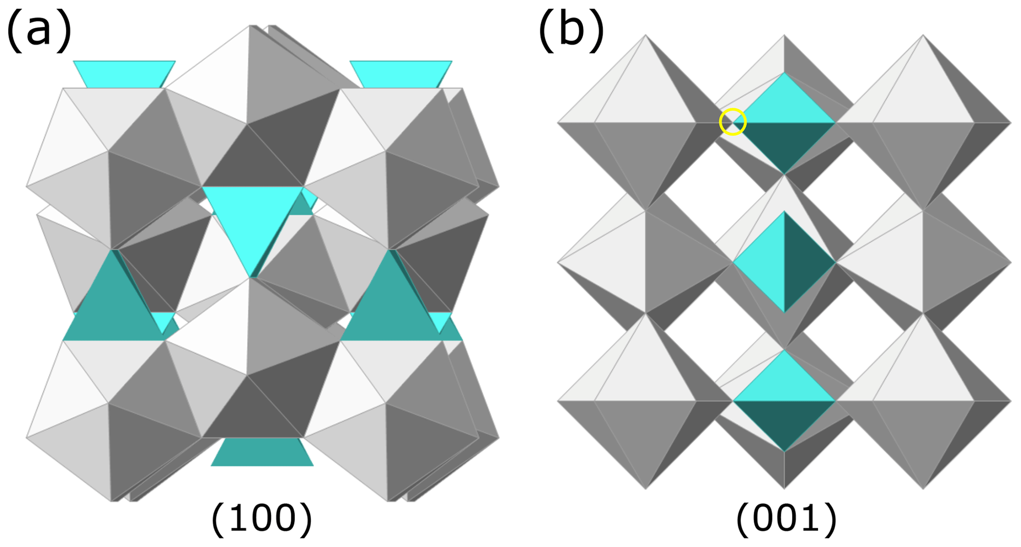
Figure 19The zircon crystal structure (Hazen and Finger, 1979; Finch and Hanchar, 2003) rendered using CrystalMaker® software. ZrO8 polyhedra are in light gray and SiO4 tetrahedra are in teal. (a) Projection on (100) looking down the a axis. (b) Projection on (001) looking down the c axis. The yellow circle highlights the corner-sharing bonds between the SiO4 tetrahedra and the ZrO8 polyhedra.
Radial or concentric fracturing related to internal stresses caused by volume expansion of radiation-damaged domains is a common feature in zircon (Chakoumakos et al., 1987; Lee and Tromp, 1995). Fracturing has also been attributed to differential stresses caused by volume reduction of damaged domains during annealing (Geisler et al., 2001a, 2002). CL images of annealed AS3 zircon illustrate that fractures related to radiation damage zoning are indeed common (Fig. 3a.I–III). Some of these fractures exhibit evidence of hydrothermal alteration, indicating that they are geological in nature (Fig. 3a.I). We consider dual radiation damage accumulation and annealing fracturing mechanisms to best explain why some residue fractures cross-cut zones of relatively high damage, while others cross-cut zones of relatively low damage (Fig. 10a). Radiation damage zoning fracturing mechanisms also explain why complex fracture networks are spatially restricted to certain zones (Figs. 10a, 11a).
Radial fractures are evident around dissolved melt inclusions in AS3 residues (Fig. 9a–b), and fractures that cross-cut mineral inclusions are common in both annealed SAM-47 samples and chemically abraded residues (Figs. 3b, 12d–e). BSE images of unannealed SAM-47 grains confirm that some fractures formed prior to the thermal annealing; however, we consider it likely that some fractures developed during thermal annealing at 900 ∘C, since zircon and inclusions have different coefficients of thermal expansion (e.g., Subbarao et al., 1990; Hovis et al., 2015). Stress fractures around inclusions have long been used to identify heat treatment in gemstones (Crowningshield and Nassau, 1981; Nassau, 1981).
While fractures related to radiation damage zoning and inclusions are the major highways providing acid access to crystal interiors, SE images of overlapping etch pits indicate that acid also percolates across regions with high defect densities including zones of higher radiation damage (Figs. 10a, 11) and regions with dislocation loops (Fig. 10a–iii). Increasing the temperature or duration of acid leaching results in more pronounced and interconnected etching textures on grain surfaces, wider acid paths, and the formation of more complex dissolution networks within crystal cores.
4.1.2 Lower-damage grains (∼ 6 × 10¹⁵ to 7 × 10¹⁷ α g−1)
The mechanics of zircon dissolution are considerably different for lower-damage samples KR18-04 and BOM2A. Fractures spatially associated with large mineral inclusions still play an important role as acid conduits to grain interiors (Figs. 14d, 16a, 17a). Fractures may be geological in nature or form during thermal annealing (Crowningshield and Nassau, 1981; Nassau, 1981; Subbarao et al., 1990; Hovis et al., 2015). Fracturing related to radiation damage zoning, however, does not meaningfully contribute to zircon dissolution in samples with lower radiation damage and more muted intra-crystalline variations.
Other mechanisms by which acid reaches a grain interior include via the dissolution of surface-reaching inclusions (Figs. 14d, 15a, 16d) and the percolation of acid across regions with higher defect densities and overlapping etch pits (Figs. 15, 16a, 17a–b). In some samples, chemical abrasion dissolves large volumes from crystal cores without clear structural reasons (Figs. 15c–d, 17e). This could reflect the dissolution of zones with more radiation damage, but the pattern of the dissolved material does not obviously conform to the zonation patterns expected for these samples. Combined, these various acid paths lead to the dissolution of some – but not all – interior inclusions and some zones with higher degrees of radiation damage.
Importantly, µCT measurements indicate that dissolution in highly crystalline material is crystallographically controlled and strongly anisotropic. Most dissolution occurs along the c axis. Etch pits preserved on (100) suggest that dissolution along the a axis is mostly limited to the dissolution of defects that intersect the grain surface. In the (100) and (010) projections of the zircon structure ZrO8 polyhedra share edges with adjacent ZrO8 polyhedra and SiO4 tetrahedra (Fig. 19) (Hazen and Finger, 1979; Finch and Hanchar, 2003), whereas in the (001) projection of the zircon structure, ZrO8 polyhedra share edges with adjacent ZrO8 polyhedra and corners with adjacent SiO4 tetrahedra. We infer that corner-sharing bonds in the (001) plane are easier to break during dissolution than the solely edge-sharing bonds in the (100) and (010) planes, causing faster dissolution along the c axis. Increasing the leaching temperature from 180 to 210 ∘C leads a more significant shortening of a crystal's aspect ratio and greater volume loss. In lower-damage grains that lack fractures, surface-reaching inclusions, and interconnected defect zones, grains predominantly dissolve from rim to core along the crystal's c axis (Figs. 14a, 15b, and 16c).
In the two samples analyzed, leaching temperature and a crystal's bulk radiation damage have the strongest control over volume loss. Results for BOM2A show that crystals with very high aspect ratios might dissolve more slowly than more equant grains, since dissolution along the c axis is the rate-limiting process. A grain's initial surface-to-volume ratio does not affect volume loss.
4.2 Implications for ID-TIMS U–Pb geochronology
4.2.1 Zircon U–Pb ages and trace element analyses
The goal of this study is to construct a mechanistic understanding of zircon dissolution and identify possible implications for U–Pb dating and coupled trace element analyses upon which future geochronological and geochemical investigations – such as the single-crystal stepwise partial dissolution experiments that are currently underway by authors AJM and BS – can build.
As discussed above, how a zircon dissolves strongly depends on its initial radiation damage content, the distribution of radiation damage and other defects within the crystals, and associated fractures. Dissolution also depends on the size and distribution of inclusions within a grain and the extent to which fractures develop around these inclusions. To a lesser degree, crystal morphology also affects dissolution. As such, the effectiveness of any chemical abrasion protocol will inherently be sample-dependent.
Here we briefly consider the idealized case of a concentrically zoned magmatic zircon. This discussion focuses on the dissolution of an intact single crystal; some ID-TIMS U–Pb studies analyze polished half-grains or targeted portions of a single crystal. Magmatic crystallization of zircon occurs over a period of time within a magma chamber. As such, zircon cores are intrinsically older than rims and often differ compositionally. A rim-to-core model for zircon dissolution implicitly suggests that dissolving more zircon during chemical abrasion by either increasing the temperature or duration of leaching will remove a greater portion of a crystal's rim and bias its U–Pb date and trace element content toward an older value and core composition, respectively. This is especially concerning for geochronological studies of volcanic rocks for which the youngest U–Pb date or population of dates is often taken to represent the age of a volcanic eruption.
Our results suggest that the majority of zircon crystals evaluated in this study do not predominantly dissolve from rim to core. While increasing the intensity of chemical abrasion leads to greater volume loss, much of that added loss comes from the dissolution of interior zones. Consequently, a typical U–Pb analysis of a zircon residue is more likely to reflect the absence of soluble high-U zones irrespective of age variation within single grains. As such, analyses of zircon residues are more likely to broadly represent mixed core–rim ages and trace element compositions. The proportion of rim-to-core material will inherently be sample- and leaching-condition-dependent. Only grains with low radiation damage, few to no inclusions, and no pre-existing fractures are likely to conform to a rim-to-core dissolution model with dissolution predominantly progressing along a crystal's c axis; however, since rim material on (100) is preserved due to limited dissolution along a, a mixed core–rim age component to each analysis likely remains.
4.2.2 Inclusions and zircon trace element analyses
Integrating chemical abrasion ID-TIMS U–Pb dates with trace element analyses (TEA) of the same volume of dissolved zircon can provide important information about petrogenetic processes (Schoene et al., 2010b). The integrative TEA approach, however, broadly assumes that inclusions are also dissolved during chemical abrasion such that the final volume analyzed is zircon as opposed to a zircon–inclusion mixture. While geochronologists generally endeavor to select inclusion-free grains, this is not possible – or desired – for all zircon samples, and not all inclusions can be identified optically with a standard binocular picking scope.
The fate of inclusions during chemical abrasion has never been rigorously investigated. Our data suggest that inclusions are readily dissolved in grains with intermediate to high radiation damage densities due to the development of stress fractures that form either geologically or during thermal annealing at 900 ∘C. These findings strongly emphasize that the annealing step of chemical abrasion is important not just for minimizing leaching-induced elemental and isotopic fractionation (Mattinson, 2005, 2011), but also for building acid paths into grain interiors to dissolve inclusions. In lower-damage grains, our findings suggest that small inclusions armored by highly crystalline zircon can survive 12 h of chemical abrasion at 210 ∘C. As such, some lower-damage residues may be susceptible to inclusion contamination. Increasing the leaching temperature from 180 to 210 ∘C improves the likelihood that inclusions will be removed, but it does not guarantee it.
4.3 Imaging radiation damage zoning: implications for thermochronology
The accumulation of radiation damage in zircon has a profound impact not only on U–Pb geochronology, but also He diffusion kinetics and deep-time zircon thermochronology (Guenthner et al., 2013; Cherniak, 2019; Anderson et al., 2017, 2020b). While cathodoluminescence imaging and Raman 2D spectral mapping have previously been used to either qualitatively or quantitatively characterize the distribution of radiation damage in polished zircon grains prior to laser ablation zircon analyses (Danišík et al., 2017; Anderson et al., 2017, 2020a), finding a method for rapid and non-destructive 3D characterization of strong radiation damage zoning in unpolished grains for single-crystal zircon dating has remained elusive. µCT offers an exciting new way to quickly screen zircon grains for strong radiation damage zoning prior to analysis. Strongly zoned grains could either be excluded from datasets or corrections could be applied to account for expected intra-crystalline variations in He diffusivity. µCT data can also be used to identify mineral phases or inclusions and intergrowths that might impact He systematics (Cooperdock and Stockli, 2016, 2018; Cooperdock et al., 2022) and improve alpha ejection corrections by providing zoning information and generating more robust surface-area-to-volume estimates (Cooperdock et al., 2019).
In this study we present a microstructural investigation of four zircon samples covering a range of ages and radiation damage densities evaluated before and after chemical abrasion in HF acid in pressure digestion vessels at 180 or 210 ∘C for 4 or 12 h. Results yield new insights into the mechanics of zircon dissolution and advance µCT as an effective tool for the rapid – and non-destructive – imaging of strong radiation damage zoning in zircon in 3D.
How a zircon dissolves strongly depends on the degree of radiation damage and the nature of intra-crystalline variations. Dissolution also depends on the size and placement of inclusions. In lower-damage zircon (∼ 6 × 10¹⁵ to 7 × 10¹⁷ α g−1), dissolution is strongly anisotropic; dissolution dominantly progresses along the c axis with minimal dissolution occurring along a. Acid reaches the interior of many lower-damage crystals via the dissolution of surface-reaching inclusions, fractures that cross-cut inclusions, and the percolation of acid across closely spaced, soluble defects to remove interior zones with higher degrees of damage and some – but not all – mineral inclusions. In addition to inclusions and radiation damage, acid also preferentially attacks intrinsic defects such as dislocation loops.
In higher-damage samples (2 × 10¹⁷ to > 1 × 10¹⁹ α g−1), acid readily dissolves low-density, high-damage rims and regularly accesses crystal cores to dissolve inclusions and interior zones with higher degrees of damage, resulting in a more crystalline residue. The most common acid paths into the interior of the higher-damage samples analyzed are planar fractures associated with radiation damage zoning, fractures that form around inclusions, and acid percolation across regions with high defect densities, which forms sponge-like textures. Fractures reflect differential stress caused by volume expansion and/or reduction of radiation-damaged domains and inclusions. Some fractures are geological in nature, but a subset of fractures formed during the thermal annealing step conducted prior to leaching (900 ∘C for 48 h); these results highlight the important role that the annealing step of chemical abrasion plays in generating pathways for acid to reach crystal interiors.
Increasing the leaching temperature or duration leads to the development of wider acid paths, more extensive dissolution networks, and the development of deeper sponge-like surface textures. In the lower-damage samples analyzed, increasing the leaching temperature by 30 ∘C resulted in an increase in volume loss of up to ∼ 40 %.
The effectiveness of any chemical abrasion protocol for ID-TIMS U–Pb geochronology will ultimately be sample-dependent. Most residue dates reflect a mixture of core and rim material, although the proportion of rim relative to core is expected to be both sample- and leaching-condition-dependent. Future microstructural investigations should focus on a wider range of zircon ages, morphologies, and geological environments of formation to help build a broader intuition for how different zircon populations dissolve. Other future studies could integrate textural data with geochemical and geochronological analyses of leachates and residues to further elucidate the mechanics of dissolution. Studies that evaluate how different annealing conditions affect zircon micro-fracturing or the rate of dissolution would also be beneficial.
All data presented are included in this paper or the Supplement.
The supplement related to this article is available online at: https://doi.org/10.5194/gchron-5-127-2023-supplement.
AJM designed and conducted the experiments. IK helped with 3D rendering of µCT data using Dragonfly software. BS and RAK contributed to data interpretation in the Discussion section. AJM prepared the figures and papers. BS, IK, and RAK contributed editorial feedback.
The contact author has declared that none of the authors has any competing interests.
Publisher's note: Copernicus Publications remains neutral with regard to jurisdictional claims in published maps and institutional affiliations.
We would like to thank Jessie Maisano of the University of Texas High-Resolution CT Facility for helping us to acquire µCT data during the height of the global pandemic and Tom Duffy of Princeton University for use of his Raman system. Thank you also to Mami Takehara of the National Institute of Polar Research in Tokyo, Japan, for providing the hydrothermally altered AS3 zircon crystals used in this study. We are indebted to Tyler McKanna for providing computing resources, and we thank Dawid Szymanowksi for many hours of valuable discussion. We would also like to acknowledge the constructive commentary from the geochronology community, reviewers, and editor – Charles Magee, Magdalena Huyskens, Fernando Corfu, Lutz Nasdala, and Daniel Condon – that helped strengthen this paper.
This work was supported by research funds provided by the Department of Geosciences at Princeton University granted to Alyssa J. McKanna as part of her Harry Hess Postdoctoral Fellowship.
This paper was edited by Klaus Mezger and reviewed by Fernando Corfu and Daniel Condon.
Anderson, A. J., Hodges, K. V., and van Soest, M. C.: Empirical constraints on the effects of radiation damage on helium diffusion in zircon, Geochim. Cosmochim. Ac., 218, 308–322, https://doi.org/10.1016/j.gca.2017.09.006, 2017.
Anderson, A. J., Hanchar, J. M., Hodges, K. V., and van Soest, M. C.: Mapping radiation damage zoning in zircon using Raman spectroscopy: Implications for zircon chronology, Chem. Geol., 538, 119494, https://doi.org/10.1016/j.chemgeo.2020.119494, 2020a.
Anderson, A. J., van Soest, M. C., Hodges, K. V., and Hanchar, J. M.: Helium diffusion in zircon: Effects of anisotropy and radiation damage revealed by laser depth profiling, Geochim. Cosmochim. Ac., 274, 45–62, https://doi.org/10.1016/j.gca.2020.01.049, 2020b.
Barley, M. and Pickard, A.: An extensive, crustally-derived, 3325 to 3310 ma silicic volcanoplutonic suite in the eastern Pilbara craton: evidence from the Kelly Belt, Mcphee Dome and Corunna Downs Batholith, Precambrian Res., 96, 41–62, 1999.
Basu, A. R., Chakrabarty, P., Szymanowski, D., Ibañez-Mejia, M., Schoene, B., Ghosh, N., and Georg, R. B.: Widespread silicic and alkaline magmatism synchronous with the Deccan Traps flood basalts, India, Earth Planet. Sc. Lett., 552, 116616, https://doi.org/10.1016/j.epsl.2020.116616, 2020.
Bowring, S. A. and Schmitz, M. D.: High-precision U-Pb zircon geochronology and the stratigraphic record, in: Reviews in Mineralogy and Geochemistry Zircon, Vol. 53, edited by: Hanchar, J. M. and Hoskin, P. W. O., 305–326, https://doi.org/10.2113/0530305, 2003.
Chakoumakos, B. C., Murakami, T., Lumpkin, G. R., and Ewing, R. C.: Alpha-decay induced fracturing in zircon: The transition from the crystalline to the metamict state, Science, 236, 1556–1559, 1987.
Cherniak, D. J.: Diffusion of helium in radiation-damaged zircon, Chem. Geol., 529, 119308, https://doi.org/10.1016/j.chemgeo.2019.119308, 2019.
Cooperdock, E. H. G. and Stockli, D. F.: Unraveling alteration histories in serpentinites and associated ultramafic rocks with magnetite (U-Th)/He geochronology, Geology, 44, 967–970, https://doi.org/10.1130/g38587.1, 2016.
Cooperdock, E. H. G. and Stockli, D. F.: Dating exhumed peridotite with spinel (U–Th)/He chronometry, Earth Planet. Sc. Lett., 489, 219–227, https://doi.org/10.1016/j.epsl.2018.02.041, 2018.
Cooperdock, E. H. G., Ketcham, R. A., and Stockli, D. F.: Resolving the effects of 2-D versus 3-D grain measurements on apatite age data and reproducibility, Geochronology, 1, 17–41, https://doi.org/10.5194/gchron-1-17-2019, 2019.
Cooperdock, E. H. G., Hofmann, F., Tibbetts, R. M. C., Carrera, A., Takase, A., and Celestian, A. J.: Technical note: Rapid phase identification of apatite and zircon grains for geochronology using X-ray micro-computed tomography, Geochronology, 4, 501–515, https://doi.org/10.5194/gchron-4-501-2022, 2022.
Crowningshield, R. and Nassau, K.: The Heat and Diffusion Treatment of Natural and Synthetic Sapphires, J. Gemmology, 17, 528–541, https://doi.org/10.15506/jog.1981.17.8.528, 1981.
Danišík, M., McInnes, B. I. A., Kirkland, C. L., McDonald, B. J., Evans, N. J., and Becker, T.: Seeing is believing: Visualization of He distribution in zircon and implications for thermal history reconstruction on single crystals, Sci. Adv., 3, e1601121, https://doi.org/10.1126/sciadv.1601121, 2017.
Davydov, V. I., Crowley, J. L., Schmitz, M. D., and Poletaev, V. I.: High-precision U-Pb zircon age calibration of the global Carboniferous time scale and Milankovitch band cyclicity in the Donets Basin, eastern Ukraine, Geochem. Geophy. Geosy., 11, Q0AA04, https://doi.org/10.1029/2009gc002736, 2010.
Ewing, R. C., Meldrum, A., Wang, L., Weber, W. J., and Corrales, L. R.: Radiation effects in zircon, Rev. Mineral. Geochem., 53, 387–425, https://doi.org/10.2113/0530387, 2003.
Finch, R. J. and Hanchar, J. M.: Structure and chemistry of zircon and zircon-group minerals, Rev. Mineral. Geochem., 53, 1–25, https://doi.org/10.2113/0530001, 2003.
Geisler, T., Pidgeon, R. T., van Bronswijk, W., and Pleysier, R.: Kinetics of thermal recovery and recrystallization of partially metamict zircon: a Raman spectroscopic study, Eur. J. Mineral., 13, 1163–1176, https://doi.org/10.1127/0935-1221/2001/0013-1163, 2001a.
Geisler, T., Ulonska, M., Schleicher, H., Pidgeon, R. T., and van Bronswijk, W.: Leaching and differential recrystallization of metamict zircon under experimental hydrothermal conditions, Contrib. Mineral. Petr., 141, 53–65, https://doi.org/10.1007/s004100000202, 2001b.
Geisler, T., Pidgeon, R. T., van Bronswijk, W., and Kurtz, R.: Transport of uranium, thorium, and lead in metamict zircon under low-temperature hydrothermal conditions, Chem. Geol., 191, 141–154, https://doi.org/10.1016/s0009-2541(02)00153-5, 2002.
Ginster, U., Reiners, P. W., Nasdala, L., and Chutimun Chanmuang N.: Annealing kinetics of radiation damage in zircon, Geochim. Cosmochim. Ac., 249, 225–246, https://doi.org/10.1016/j.gca.2019.01.033, 2019.
Gleadow, A. J. W., Hurford, A. J., and Quaife, R. D.: Fission track dating of zircon: Improved etching techniques, Earth Planet. Sc. Lett., 33, 273–276, https://doi.org/10.1016/0012-821x(76)90235-1, 1976.
Guenthner, W. R., Reiners, P. W., Ketcham, R. A., Nasdala, L., and Giester, G.: Helium diffusion in natural zircon: Radiation damage, anisotropy, and the interpretation of zircon (U-Th)/He thermochronology, Am. J. Sci., 313, 145–198, https://doi.org/10.2475/03.2013.01, 2013.
Hanchar, J. M., Finch, R. J., Hoskin, P. W. O., Watson, E. B., Cherniak, D. J., and Mariano, A. N.: Rare earth elements in synthetic zircon: part 1. Synthesis, and rare earth element and phosphorus doping, Am. Mineral., 86, 667–680, 2001.
Härtel, B., Jonckheere, R., Wauschkuhn, B., and Ratschbacher, L.: The closure temperature(s) of zircon Raman dating, Geochronology, 3, 259–272, https://doi.org/10.5194/gchron-3-259-2021, 2021.
Hazen, R. M. and Finger, L. W.: Crystal structure and compressibility of zircon at high pressure, Am. Mineral., 64, 196–201, 1979.
Holland, H. D. and Gottfried, D.: The effect of nuclear radiation on the structure of zircon, Acta Crystallogr., 8, 291–300, https://doi.org/10.1107/s0365110x55000947, 1955.
Hovis, G., Abraham, T., Hudacek, W., Wildermuth, S., Scott, B., Altomare, C., Medford, A., Conlon, M., Morris, M., Leaman, A., Almer, C., Tomaino, G., and Harlov, D.: Thermal expansion of F-Cl apatite crystalline solutions, Am. Mineral., 100, 1040–1046, https://doi.org/10.2138/am-2015-5176, 2015.
Huyskens, M. H., Zink, S., and Amelin, Y.: Evaluation of temperature-time conditions for the chemical abrasion treatment of single zircons for U–Pb geochronology, Chem. Geol., 438, 25–35, https://doi.org/10.1016/j.chemgeo.2016.05.013, 2016.
Itoh, N. and Shirono, K.: Reliable estimation of Raman shift and its uncertainty for a non-doped Si substrate (NMIJ CRM 5606-a), J. Raman Spectrosc., 51, 2496–2504, https://doi.org/10.1002/jrs.6003, 2020.
Jonckheere, R.: On the densities of etchable fission tracks in a mineral and co-irradiated external detector with reference to fission-track dating of minerals, Chem. Geol., 200, 41–58, https://doi.org/10.1016/s0009-2541(03)00116-5, 2003.
Jonckheere, R. and Van den Haute, P.: Observations on the geometry of etched fission tracks in apatite: Implications for models of track revelation, Am. Mineral., 81, 1476–1493, 1996.
Jonckheere, R., Enkelmann, E., and Stübner, K.: Observations on the geometries of etched fission and alpha-recoil tracks with reference to models of track revelation in minerals, Radiat. Meas., 39, 577–583, https://doi.org/10.1016/j.radmeas.2004.08.008, 2005.
Jonckheere, R., Aslanian, C., Wauschkuhn, B., and Ratschbacher, L.: Fission-track etching in apatite: A model and some implications, Am. Mineral., 107, 1190–1200, https://doi.org/10.2138/am-2022-8055, 2022.
Jones, S., Kohn, B., and Gleadow, A.: Etching of fission tracks in monazite: Further evidence from optical and focused ion beam scanning electron microscopy, Am. Mineral., 107, 1065–1073, https://doi.org/10.2138/am-2022-8002, 2022.
Ketcham, R. A., Guenthner, W. R., and Reiners, P. W.: Geometric analysis of radiation damage connectivity in zircon, and its implications for helium diffusion, Am. Mineral., 98, 350–360, https://doi.org/10.2138/am.2013.4249, 2013.
Krishnam, R. S.: Raman spectrum of quartz, Nature, 155, 142, https://doi.org/10.1038/155452a0, 1945.
Lee, J. K. W. and Tromp, J.: Self-induced fracture generation in zircon, J. Geophys. Res.-Sol. Ea., 100, 17753–17770, https://doi.org/10.1029/95jb01682, 1995.
MacLennan, S. A., Eddy, M. P., Merschat, A. J., Mehra, A. K., Crockford, P. W., Maloof, A. C., Southworth, C. S., and Schoene, B.: Geologic evidence for an icehouse Earth before the Sturtian global glaciation, Sci. Adv., 6, eaay6647, https://doi.org/10.1126/sciadv.aay6647, 2020.
Mattinson, J. M.: Zircon U–Pb chemical abrasion (“CA-TIMS”) method: Combined annealing and multi-step partial dissolution analysis for improved precision and accuracy of zircon ages, Chem. Geol., 220, 47–66, https://doi.org/10.1016/j.chemgeo.2005.03.011, 2005.
Mattinson, J. M.: Extending the Krogh legacy: development of the CA-TIMS method for zircon U-Pb geochronology, Can. J. Earth Sci., 48, 95–105, https://doi.org/10.1139/e10-023, 2011.
Mattinson, J. M., Graubard, C. M., Parkinson, D. L., and McClelland, W. C.: U-Pb reverse discordance in zircon: The role of fine-scale oscillatory zoning and sub-micron transport of Pb, in: Earth Processes Reading the Isotopic Code, edited by: Basu, A. and Hart, S., American Geophysical Union, Washington D.C., USA, 355–370, 1996.
Meldrum, A., Boatner, L. A., Weber, W. J., and Ewing, R. C.: Radiation damage in zircon and monazite, Geochim. Cosmochim. Ac., 62, 2509–2520, https://doi.org/10.1016/s0016-7037(98)00174-4, 1998.
Meyers, S. R., Siewert, S. E., Singer, B. S., Sageman, B. B., Condon, D. J., Obradovich, J. D., Jicha, B. R., and Sawyer, D. A.: Intercalibration of radioisotopic and astrochronologic time scales for the Cenomanian-Turonian boundary interval, Western Interior Basin, USA, Geology, 40, 7–10, https://doi.org/10.1130/g32261.1, 2012.
Mezger, K. and Krogstad, E. J.: Interpretation of discordant U-Pb zircon ages: An evaluation, J. Metamorph. Geol., 15, 127–140, https://doi.org/10.1111/j.1525-1314.1997.00008.x, 1997.
Mundil, R., Ludwig, K. R., Metcalfe, I., and Renne, P. R.: Age and timing of the Permian mass extinctions: U/Pb dating of closed-system zircons, Science, 305, 1760–1763, https://doi.org/10.1126/science.1101012, 2004.
Murakami, T., Chakoumakos, B. C., Ewing, R. C., Lumpkin, G. R., and Weber, W. J.: Alpha-decay event damage in zircon, Am. Mineral., 76, 1510–1532, 1991.
Nasdala, L., Irmer, G., and Wolf, D.: The degree of metamictization in zircon: a Raman spectroscopic study, Eur. J. Mineral., 7, 471–478, https://doi.org/10.1127/ejm/7/3/0471, 1995.
Nasdala, L., Pidgeon, R. T., Wolf, D., and Irmer, G.: Metamictization and U-Pb isotopic discordance in single zircons: a combined Raman microprobe and SHRIMP ion probe study, Mineral. Petrol., 62, 1–27, https://doi.org/10.1007/bf01173760, 1998.
Nasdala, L., Wenzel, M., Vavra, G., Irmer, G., Wenzel, T., and Kober, B.: Metamictisation of natural zircon: accumulation versus thermal annealing of radioactivity-induced damage, Contrib. Mineral. Petr., 141, 125–144, https://doi.org/10.1007/s004100000235, 2001.
Nasdala, L., Reiners, P. W., Garver, J. I., Kennedy, A. K., Stern, R. A., Balan, E., and Wirth, R.: Incomplete retention of radiation damage in zircon from Sri Lanka, Am. Mineral., 89, 219–231, 2004.
Nassau, K.: Heat treating ruby and sapphire: Technical aspects, Gems Gemol., 17, 121–131, https://doi.org/10.5741/gems.17.3.121, 1981.
Paces, J. B. and Miller, J. D.: Precise U-Pb ages of Duluth Complex and related mafic intrusions, northeastern Minnesota: Geochronological insights to physical, petrogenetic, paleomagnetic, and tectonomagmatic processes associated with the 1.1 Ga Midcontinent Rift System, J. Geophys. Res.-Sol. Ea., 98, 13997–14013, https://doi.org/10.1029/93jb01159, 1993.
Palenik, C. S., Nasdala, L., and Ewing, R. C.: Radiation damage in zircon, Am. Mineral., 88, 770–781, https://doi.org/10.2138/am-2003-5-606, 2003.
Schmitz, M. D. and Davydov, V. I.: Quantitative radiometric and biostratigraphic calibration of the Pennsylvanian–Early Permian (Cisuralian) time scale and pan-Euramerican chronostratigraphic correlation, GSA Bull., 124, 549–577, https://doi.org/10.1130/b30385.1, 2012.
Schmitz, M. D., Bowring, S. A., and Ireland, T. R.: Evaluation of Duluth Complex anorthositic series (AS3) zircon as a U-Pb geochronological standard: new high-precision isotope dilution thermal ionization mass spectrometry results, Geochim. Cosmochim. Ac., 67, 3665–3672, https://doi.org/10.1016/s0016-7037(03)00200-x, 2003.
Schoene, B.: Treatise on Geochemistry (Second Edition), in: Treatise on Geochemistry, Vol. 4, edited by: Holland, H. D. and Turekian, K. K., Treatise on Geochemistry, Elsevier Ltd., 341–378, https://doi.org/10.1016/b978-0-08-095975-7.00310-7, 2014.
Schoene, B., Guex, J., Bartolini, A., Schaltegger, U., and Blackburn, T. J.: Correlating the end-Triassic mass extinction and flood basalt volcanism at the 100 ka level, Geology, 38, 387–390, https://doi.org/10.1130/g30683.1, 2010a.
Schoene, B., Latkoczy, C., Schaltegger, U., and Günther, D.: A new method integrating high-precision U–Pb geochronology with zircon trace element analysis (U–Pb TIMS-TEA), Geochim. Cosmochim. Ac., 74, 7144–7159, https://doi.org/10.1016/j.gca.2010.09.016, 2010b.
Smithies, R. H., Champion, D. C., and Cassidy, K. F.: Formation of Earth's early Archaean continental crust, Precambrian Res., 127, 89–101, 2003.
Subbarao, E. C., Agrawal, D. K., McKinstry, H. A., Sallese, C. W., and Roy, R.: Thermal expansion of compounds of zircon structure, J. Am. Ceram. Soc., 73, 1246–1252, https://doi.org/10.1111/j.1151-2916.1990.tb05187.x, 1990.
Swanson-Hysell, N. L., Hoaglund, S. A., Crowley, J. L., Schmitz, M. D., Zhang, Y., and Miller, J. D.: Rapid emplacement of massive Duluth Complex intrusions within the North American Midcontinent Rift, Geology, 49, 185–189, https://doi.org/10.1130/g47873.1, 2020.
Takehara, M., Horie, K., Hokada, T., and Kiyokawa, S.: New insight into disturbance of U-Pb and trace-element systems in hydrothermally altered zircon via SHRIMP analyses of zircon from the Duluth Gabbro, Chem. Geol., 484, 168–178, https://doi.org/10.1016/j.chemgeo.2018.01.028, 2018.
Trachenko, K., Dove, M. T., and Salje, E. K. H.: Structural changes in zircon under α-decay irradiation, Phys. Rev. B, 65, 180102, https://doi.org/10.1103/physrevb.65.180102, 2002.
Váczi, T.: A new, simple approximation for the deconvolution of instrumental broadening in spectroscopic band profiles, Appl. Spectrosc., 68, 1274–1278, https://doi.org/10.1366/13-07275, 2014.
Váczi, T. and Nasdala, L.: Electron-beam-induced annealing of natural zircon: a Raman spectroscopic study, Phys. Chem. Miner., 44, 389–401, https://doi.org/10.1007/s00269-016-0866-x, 2017.
van Kranendonk, M. J., Hugh Smithies, R., Hickman, A. H., and Champion, D.: Review: secular tectonic evolution of Archean continental crust: interplay between horizontal and vertical processes in the formation of the Pilbara Craton, Australia, Terra Nova, 19, 1–38, https://doi.org/10.1111/j.1365-3121.2006.00723.x, 2007.
Weber, W. J.: Radiation-induced defects and amorphization in zircon, J. Materials Res., 5, 2687–2697, 1990.
Widmann, P., Davies, J. H. F. L., and Schaltegger, U.: Calibrating chemical abrasion: Its effects on zircon crystal structure, chemical composition and U-Pb age, Chem. Geol., 511, 1–10, https://doi.org/10.1016/j.chemgeo.2019.02.026, 2019.
Yamada, R., Tagami, T., Nishimura, S., and Ito, H.: Annealing kinetics of fission tracks in zircon: an experimental study, Chem. Geol., 122, 249–258, https://doi.org/10.1016/0009-2541(95)00006-8, 1995.
Yamada, R., Murakami, M., and Tagami, T.: Statistical modelling of annealing kinetics of fission tracks in zircon; Reassessment of laboratory experiments, Chem. Geol., 236, 75–91, https://doi.org/10.1016/j.chemgeo.2006.09.002, 2007.
Zhang, M., Salje, E. K. H., Capitani, G. C., Leroux, H., Clark, A. M., Schlüter, J., and Ewing, R. C.: Annealing of alpha-decay damage in zircon: a Raman spectroscopic study, J. Phys. Condens. Matter, 12, 3131, https://doi.org/10.1088/0953-8984/12/13/321, 2000.