the Creative Commons Attribution 4.0 License.
the Creative Commons Attribution 4.0 License.
 | 03 Nov 2025
Technical note: Improved calculation of volume, FT correction, and other derived data for polished zircon (U-Th)/He thermochronology
Polishing mounted zircon crystals prior to bulk grain (U-Th)/He thermochronology analysis provides opportunities for characterizing and subsampling each grain via in situ methods to obtain additional information relevant for (U-Th)/He date interpretation and the broader geologic questions of interest. However, polishing introduces complications for classifying grain geometry and determining grain volume (V), on which many derived (U-Th)/He data partially depend. Derived data that depend on volume include isotope concentrations, effective uranium (eU; a proxy for radiation damage), and alpha-ejection correction factors (FT), which are used to correct (U-Th)/He dates. These derived data are integral to interpreting (U-Th)/He dates, and, without a way to accurately calculate these values for polished grains, a choice must be made between polishing zircon to provide robust in situ data at the expense of the thermochronologic data or not polishing and limiting in situ data to grain rims or one-dimensional depth profiles. To address this issue, this paper presents a comprehensive protocol for calculating volume and alpha-ejection surface area for polished zircon grain fragments, from which additional data, including eU and FT, are derived. This protocol is implemented after grains have been polished and in situ measurements have been made and can easily be integrated into existing workflows for characterizing and measuring grains for conventional (U-Th)/He analysis. An R script accompanying this paper can be used to perform the required calculations and assign uncertainties during analytical data reduction. Applying the new protocol to a synthetic dataset covering a range of zircon geometries, sizes, and grinding conditions shows that the method is an improvement over existing methods to calculate polished grain FT, which only apply to a small subset of possible grain geometries and grinding conditions. The new protocol also calculates all derived data and uncertainties necessary and recommended for (U-Th)/He data reporting, aside from the (U-Th)/He dates themselves, to facilitate integrations with existing data reporting, date interpretation, and thermal history modeling.
- Article
(3851 KB) - Full-text XML
-
Supplement
(18877 KB) - BibTeX
- EndNote


(U-Th)/He thermochronology dates and associated data are derived from analytical measurements of parent and daughter isotopes and the volume (V) of the individual mineral grains analyzed. These “derived data” include alpha-ejection correction factors (FT), FT-equivalent spherical radius (RFT), effective uranium (eU), and parent isotope concentrations, and they are essential for interpreting dates and making other geological inferences. FT corrections are applied to account for He lost through alpha-ejection and directly affect the reported (U-Th)/He dates (Farley, 2002). RFT is used to compare grain size and approximate He diffusion domain size in thermal history modeling (Flowers et al., 2022a, b; Ketcham et al., 2011). eU can affect how the thermal history of the grain is interpreted (e.g., Flowers et al., 2022b; Guenthner et al., 2013). Other derived data, such as isotope concentrations, may be used to characterize additional aspects of the samples' geologic history (e.g., sediment recycling history; Dröllner et al., 2022). Accurate V calculation is therefore critically important, as it informs all these other data.
In addition to V dependence, FT also depends on another variable related to grain morphology: alpha-ejection surface area, or the surface area of the grain over which alpha particles are ejected (SAα). Both V and SAα are typically determined for whole crystals by classifying each grain as one of several idealized geometries based on visual inspection and making two-dimensional (2D) measurements of grain size or using three-dimensional imaging methods (Cooperdock et al., 2019; Glotzbach et al., 2019; Ketcham et al., 2011; Reiners et al., 2005; Zeigler et al., 2023, 2024). However, many applications of (U-Th)/He thermochronology, such as detrital zircon applications, benefit from or require mounting and polishing crystals for in situ analyses to characterize chemical zonation, rare earth element abundances, U-Pb or other geochronology data, etc. prior to (U-Th)/He analysis. Grinding and polishing grains to prepare them for additional analysis removes part of the grain, resulting in grain geometries that deviate from the original whole grain and complications for calculating V and SAα for the remaining fragment. Existing whole-grain methods to calculate V and SAα (e.g., Farley, 2002; Ketcham et al., 2011; Reiners et al., 2005) are in many cases inapplicable when grains are ground and polished.
Although some previous work has addressed the effect of grinding and polishing on FT corrections (He and Reiners, 2022; Marsden et al., 2021; Reiners et al., 2007), these contributions do not address other data derived from volume and surface area and apply to specific cases that do not reflect the full range of real zircon samples or sample preparation. To address the lack of a comprehensive approach to volume-derived data for polished zircon, this contribution presents a protocol and set of equations (Appendix A) coded in an R script (Code availability) that can be integrated with existing workflows for grain characterization and (U-Th)/He thermochronology data reduction and interpretation. Values calculated under this protocol include V, SAα, volume-to-alpha-ejection-surface-area-equivalent spherical radius (RSV), mass (M), parent isotope concentrations, eU, FT, and RFT. Results of using the protocol are evaluated using a synthetic dataset encompassing a range of possible grain geometries, sizes, polishing orientations, and grinding depths (Sect. 4, Table S1 in the Supplement) and application to a real detrital zircon dataset (text in the Supplement, Table S2).
Previous work has addressed the impact of polishing or other means of removing part of the grain on derived data, particularly on FT corrections (He and Reiners, 2022; Marsden et al., 2021; Reiners et al., 2007). These contributions have largely focused on direct comparisons between FT corrections for polished grain fragments and FT corrections for corresponding whole crystals from which polished grains were derived (Marsden et al., 2021) or focused on a subset of possible polishing scenarios that do not reflect the full range of real zircon samples or sample preparation (He and Reiners, 2022; Reiners et al., 2007). A common approach to simplify FT corrections is to polish grains to a plane of symmetry (e.g., halfway through the original c-axis perpendicular width), such that the FT value of the fragment is the same as the FT value for the entire whole grain (Reiners et al., 2007). However, polishing exactly halfway is often extremely difficult, if not impossible, and inaccuracy in polishing depth can result in FT uncertainty greater than 1σ=5 % (Marsden et al., 2021). Alternatively, the same symmetry logic can be applied to crystals broken perpendicular to an axis of symmetry when the true original axis length is unknown (He and Reiners, 2022). The broken interior face of the crystal is treated as a plane of symmetry such that the fragment has the same FT as a whole grain with an axis length double the axis length of the fragment. V and SAα of the fragment can be calculated by dividing the V and SAα of the reconstructed whole grain in half. Although this approach can be applied to any crystal geometry and plane of symmetry, the He and Reiners protocol is focused on cylindrical grains polished or broken perpendicular to the c axis. For grains polished parallel to the c axis, Reiners et al. (2007) provide a protocol for a limited number of cases: cylindrical and orthorhombic prisms ground and polished to a depth between one alpha-stopping distance and less than half of the original c-axis perpendicular thickness of the crystal.
In reality, zircon encompass a range of morphologies depending on lithology and geologic history beyond what has previously been considered in the literature. Zircon can be approximated as cylinders, ellipsoids, and orthorhombic prisms with or without pyramidal terminations (commonly referred to as “tetragonal” geometries even when a- and b-axis measurements are not equivalent). The grinding and polishing orientation of individual crystals can be parallel or perpendicular to the crystallographic c axis, and, because of the natural variation in crystal size, it is common for polishing to remove a variable amount of crystal when multiple crystals are mounted and prepared together (e.g., Fig. 1a). Protocols to determine FT corrections and other derived data for polished zircon based on geometry and volume must therefore encompass these different scenarios in order to maximize the number of grains that can be used for analysis in a given sample and grain mount.
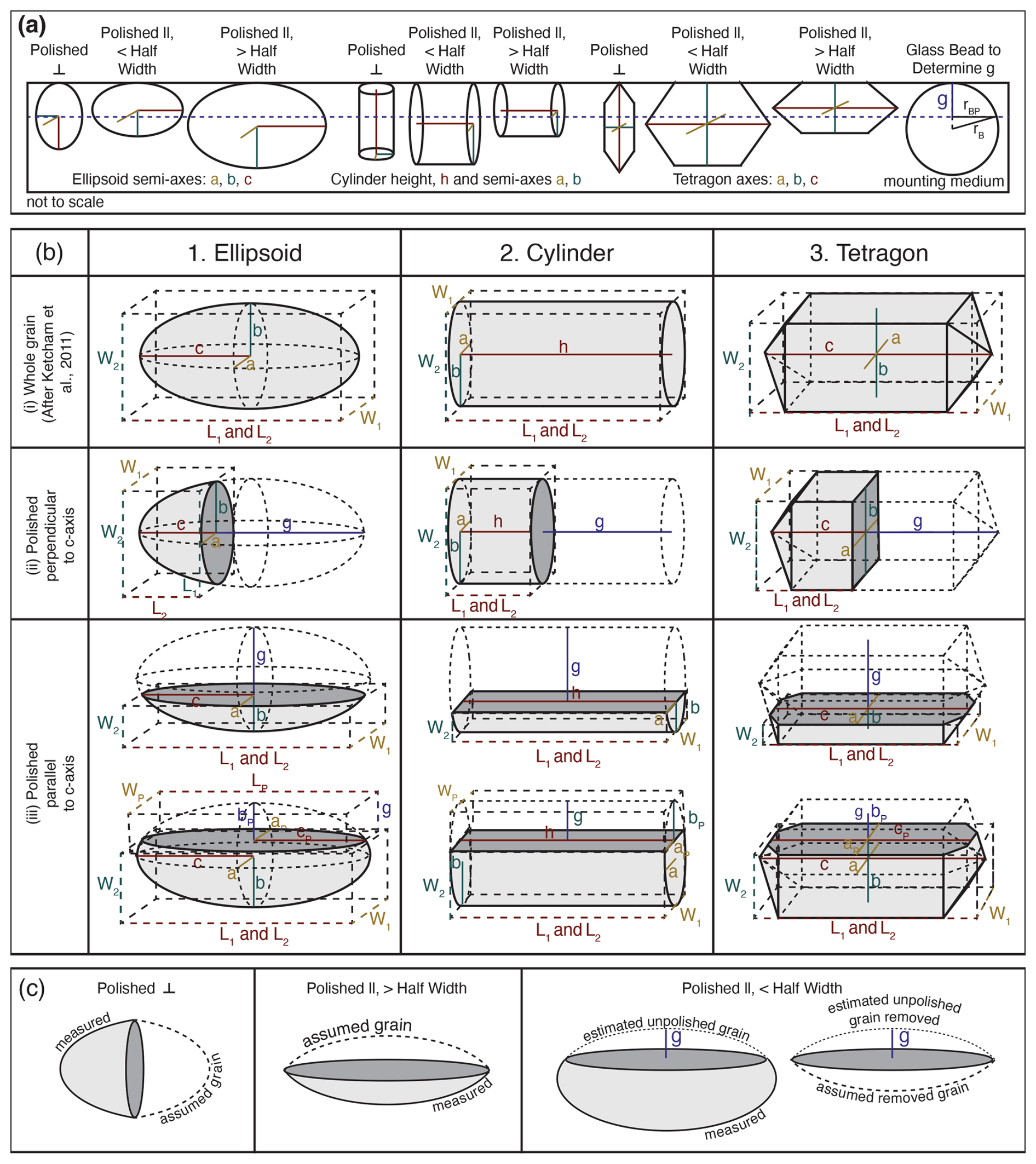
Figure 1Grain morphology impacts and the assignment of geometric parameters after grinding and polishing. (a) Schematic grain mount showing a variable amount of grain removed depending on original grain geometry, size, and orientation with respect to polishing surface (dashed line). (b) Relationship between 2D grain measurements (L1, L2, W1, W2) and geometric parameters (a, b, c, h) for each geometry expressed mathematically in Table 1. (i) Whole grains (after Ketcham et al., 2011). (ii) Grain fragments arising from polishing grains perpendicular to the c axis. (iii) Grain fragments arising from polishing grains parallel to the c axis. In all panels, the light-gray shaded region corresponds to the V calculated. The dark-gray surface is the polished surface not included in SAα. (c) Illustration of the method to calculate V and SAα as half of the “assumed grain” or estimate of the removed portion of grain from the estimated whole grain.
The protocol presented here adapts existing approaches for determining whole-grain V, SAα, and FT for ground and polished grain fragments. First, the polished grains are removed from the mounting medium and are inspected and measured using a binocular microscope with a digital camera and microscope imaging software. Grains are classified as ellipsoidal, cylindrical, or “tetragonal” geometries, which can include two, one, or no pyramidal terminations. In order to be classified as cylindrical or tetragonal, the unpolished part of the grain must include visible crystal faces that are unrelated to the polished face. For cylinders, these faces are only perpendicular to the long axis, while, for tetragonal grains, some must be parallel to the long axis (Fig. 1). If there are no observed crystal faces, the grain is classified as an ellipsoid. Like standard approaches for calculating whole-grain V (e.g., Zeigler et al., 2024), two orthogonal sets of length and width measurements (L1, W1 and L2, W2) parallel to orthogonal crystal axes are made by rotating the grain fragment (Fig. 1b). Polishing orientation is also classified as perpendicular or parallel to the crystallographic c axis based on visual inspection of the grain fragment.
Once grains have been classified and measured, V and SAα are calculated (Appendix A) by relating grain measurements to the geometric parameters of the relevant geometric classification (a, b, and c semi-axes; a and b semi-axes and height, h; or a, b, and c axes for ellipsoids, cylinders, and tetragons, respectively; Table 1, Fig. 1b). Only external grain surfaces are subject to alpha-ejection; thus the polished surface is not considered to be part of SAα. In most cases, calculating these values is accomplished by adopting the same approach as He and Reiners (2022) in which the polished grain is treated as a crystal broken along a plane of symmetry such that V and SAα of the polished fragment are half of a whole “assumed grain” created by reflecting the existing fragment across the plane of polishing (Fig. 1c). FT of the fragment is thus equal to FT of the assumed grain. This is the approach used for all grains polished perpendicular to the c axis or parallel to the c axis and greater than halfway through the original c-axis perpendicular width of the grain (Fig. 1c), which can be determined by visual inspection of the polished grain and does not require measurements of thickness pre-polishing. For grains polished parallel to the c axis and less than halfway through the original width of the grain (again, determined by visual inspection of the grain post-polishing), a different approach to determining V and SAα is used. In these cases, the original whole-grain dimensions are estimated by combining the grain measurements with the grinding depth (g) determined by measurements of spherical glass beads mounted and polished alongside the grains. Polishing depth is calculated using Eq. (1) (Pickering et al., 2020) and measurements of the radius of the polished bead surface (rBP) relative to the full bead radius (rB) (Fig. 1a).
Uncertainty on g can be determined through duplicate measurements of multiple embedded beads scattered throughout the grain mount. The estimated whole-grain dimensions are used to estimate V and SAα for the whole original grain. To calculate V and SAα of the remaining fragment, the V and SAα of the removed portion of the grain are also estimated and subtracted from the estimated whole-grain values. V and SAα of the removed portion are determined by treating removed portions of the crystals as half crystals of a whole assumed grain in the same manner as grains polished parallel to the c axis and more than halfway through the original grain width (Fig. 1c). This calculation requires additional measurements of the polished grain surface for ellipsoid and cylinder geometries: length (LP) and width (WP) of the polished face. In practice, LP and WP are often indistinguishable from L1 and W1 for small and medium grains, but, for larger grains, the difference between the polished face and total axis measurements can be much greater.
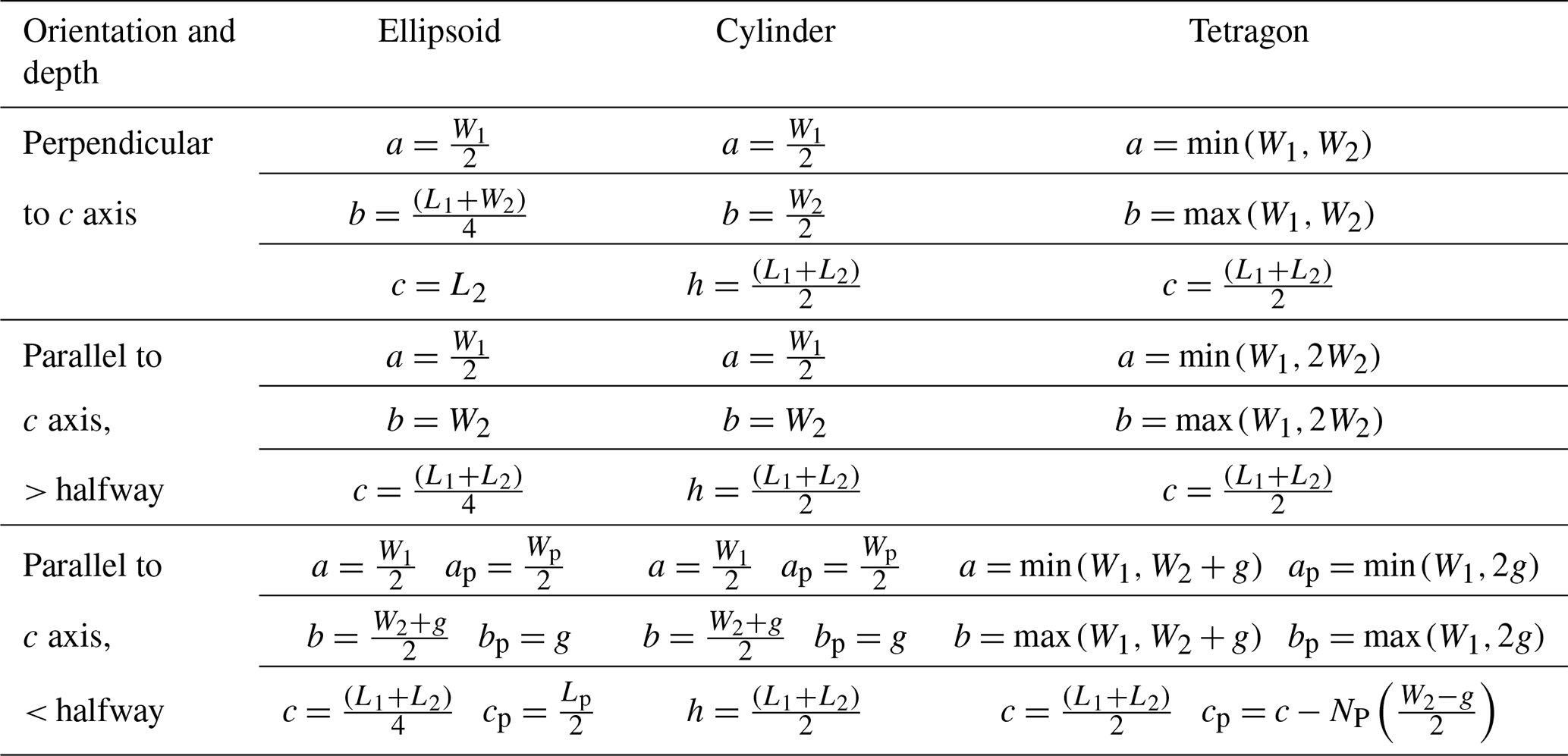
Table 1Relationship between 2D grain measurements and geometric values used to calculate volume and surface area. Grain measurements relative to each idealized geometry are shown in Fig. 1b.
Volume uncertainty reflects the assumptions made in applying an idealized geometry and human measurement error to imperfect natural zircon and is applied as 1σ=21 % or 13 % for ellipsoid or tetragonal grains, respectively, following recommendations in Zeigler et al. (2024). Volume uncertainty arising from geometric assumptions has not been quantified for cylindrical grains like it has for other geometries (Cooperdock et al., 2019; Zeigler et al., 2023, 2024), so, in the absence of this quantification, the largest quantified uncertainty for zircon from Zeigler et al. (2024), 1σ=21 %, is applied as a conservative estimate. Future work should establish a quantitative V uncertainty value and correction for cylinders, as this is a common geometry for abraded grains. SAα uncertainty is unquantified for all geometries. Data that are derived directly from volume (RSV, mass, parent isotope concentrations, and eU) are calculated using equations in Appendix A and include propagated volume uncertainty and analytical isotope measurement uncertainty when applicable. Like most whole-aliquot (U-Th)/He thermochronology data reduction, the grains are assumed to have homogenous parent isotope concentrations (e.g., no zonation). Deviation from this assumption would impact the calculated dates in similar ways to zonation in whole grains (e.g., Danišík et al., 2017; Hourigan et al., 2005).
FT depends not just on volume, but also on SAα, which is represented here using the term RSV, or volume-to-surface-area equivalent spherical radius, calculated using Eq. (2) as in Ketcham et al. (2011).
RSV serves the same function as the β term introduced by Farley (2002) to relate grain measurements to FT via a polynomial function with the general form of Eq. (3).
Polynomial coefficients a1, a2, a3, etc. are determined via series of Monte Carlo simulations of variable grains and fitting the results (e.g., Hourigan et al., 2005; Ketcham et al., 2011) and depend on alpha-stopping distance and grain geometry. For the new protocol, the FT equations and coefficients of Ketcham et al. (2011) are adopted as the basis for calculating FT (Appendix A) because they are fit to the full range of grain geometries commonly seen in natural zircon. For grains that begin whole as ellipsoids, cylinders, or tetragons without terminations, grinding and polishing results in remaining grain fragments with morphologies that are still well described by the original geometries and FT equations tailored to those geometries, such that minimal uncertainty is introduced by applying the geometry-specific coefficients of Ketcham et al. (2011) to these polished grains. The whole-grain coefficients are likely less applicable to grain geometries that change more significantly with grinding and polishing, namely tetragonal geometries with one or two terminations, and the new protocol should be applied with caution to these geometries. However, even with this limitation, the new protocol improves on existing protocols for polished grain FT values through the addition of ellipsoid geometries and a range of polishing depth beyond half of the original grain width.
In addition to isotope-specific FT values (used to calculate corrected (U-Th)/He dates), combined FT and FT-equivalent spherical radius (RFT) are calculated using equations from Cooperdock et al. (2019) (Appendix A). Combined FT is useful as a summary of overall alpha-ejection correction and for comparison with other formulations of FT (e.g., Reiners et al., 2007). RFT is commonly reported as a proxy for grain size (e.g., Flowers et al., 2022a). Isotope-specific FT uncertainties for ellipsoid and tetragonal geometries are applied following recommendations in Zeigler et al. (2024) for ellipsoid and tetragonal grain geometries; for cylindrical geometries, the larger of the recommended uncertainties for the other geometries is applied (ellipsoid: 3 %, 4 %, 4 %, and 1 % for FT,238, FT,235, FT,232, and FT,147, respectively; tetragonal/cylindrical: 3 %, 4 %, 5 %, and 1 % for FT,238, FT,235, FT,232, and FT,147, respectively). Combined FT uncertainty is propagated from isotope-specific FT values and parent isotope concentrations. Uncertainty on RFT is applied as 1σ=8 % RFT following recommendations in Zeigler et al. (2024).
A synthetic dataset (Table S1) was used to evaluate the protocol and compare with existing approaches to calculating FT values. The synthetic dataset was designed to test a range of original grain geometries, total grain sizes, grinding and polishing orientations, and grinding depths greater than the maximum average zircon alpha stopping distance ( µm; Ketcham et al., 2011). Total grain size was defined by a combination of “size” corresponding to the c-axis parallel length – generally the longest grain axis corresponding to grain length measurements L1 and L2, “width ratio” between the two c-axis perpendicular grain lengths (corresponding to a and b crystallographic axes and grain width measurements W1 and W2), and “aspect ratio” between the c-axis parallel and perpendicular axes lengths. First, whole, unpolished synthetic grains were created with sizes L1 and L2, including “smallest” (60 µm), “small” (100 µm), “medium” (150 µm), or “large” (200 µm), a range of aspect ratios where the first axis (W1), was set to 0.3–1 times the size, and a range of width ratios where the second short axis (W2) was set to 0.5–1 times W1. The range of c-axis parallel sizes was chosen to reflect sizes commonly seen in natural zircon. Aspect and width ratio ranges were chosen to reflect observed ranges of these ratios while also ensuring that grinding depth would always be greater than one alpha stopping distance. This was done to ensure no complications to interpreting FT arising from incomplete removal of the alpha-ejection rim. Grains were created in this way for all common zircon idealized geometries: ellipsoid, cylinder, and tetragons with no, one, or two terminations. “Polished grains” were then created by assigning grinding depth as a fraction of the total width or length of the grain depending on whether grains were polished parallel or perpendicular to the c axis, respectively. The range of grinding depths includes 0 (unpolished grains) and 0.25–0.75 of the total width or length.
FT results of applying the protocol developed in this contribution to the synthetic dataset show a strong dependence on geometry and size (Fig. 2a), as expected based on FT values for whole grains (Farley, 2002; Ketcham et al., 2011; Reiners et al., 2005). The Ketcham et al. (2011) FT functions and polynomial coefficients adopted in the new protocol apply to FT between 0.5 and 1: whole synthetic grains with FT<0.5 were therefore rejected from further discussion, as were polished synthetic grains based on the rejected original whole-grain dimensions, leaving FT results for 16 128 synthetic grains. Across all geometries and grain sizes, the majority of grains exhibit expected changes in FT with increasing grinding depth: polished FT is greater than whole FT up to 50 % grinding depth, and polished FT is less than whole FT above 50 %. The smallest ellipsoid grains with the lowest aspect and width ratios (e.g., Fig. 2b) are an exception to this pattern, which is likely related to partial removal of the remaining fragment's alpha-ejection rim at higher grinding depths. The largest grains exhibit the smallest differences between whole-grain and polished grain FT, but the difference increases once more than half the grain width is ground away as for other grain sizes (Fig. 2a). Very negative percent differences < −20 % that are reached at high grinding depths are likely due to the increasing differences in polished SAα from whole-grain SAα at this degree of polishing. Percent difference between whole- and polished grain FT does not vary systematically with overall grain symmetry – that is, with changes in grain aspect ratio and width ratio. Rather, the difference depends on the combination of axis measurements and other factors, such as the number of terminations in the case of tetragonal grains (Fig. 2a). Tetragonal geometries with zero terminations vary the least with polishing depth, while tetragonal geometries with two terminations vary the most. This result is not surprising given that termination morphology is heavily impacted by grinding such that the approximation becomes more and more tenuous with increasing removal of grain material. Terminations are approximated using a uniform assumption of symmetric pyramidal terminations sloped 45° to the prismatic core of the grain (Ketcham et al., 2011), which is also likely responsible for some of the unexpected behavior of these grains, as, in reality, this angle can vary from zircon to zircon.
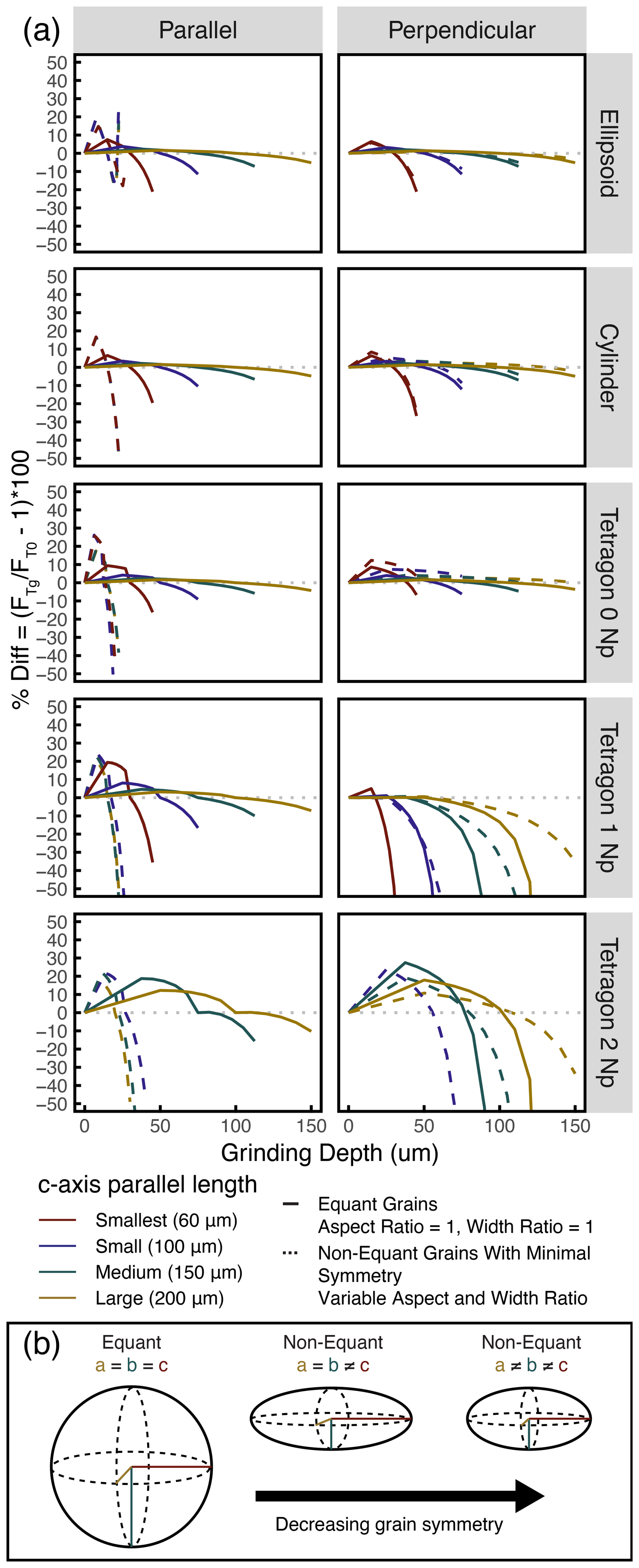
Figure 2(a) Percent difference between combined FT for ground/polished zircon and whole zircon as a function of grinding depth. Color corresponds to c-axis parallel length. Solid lines show patterns for largest equant grains in each size group (aspect ratio = 1, width ratio = 1). Dashed lines show patterns for smallest non-equant grains in each size group with minimum symmetry that meet requirements for whole-grain FT≥0.5. (b) Cartoon showing variability possible between equant and non-equant grains.
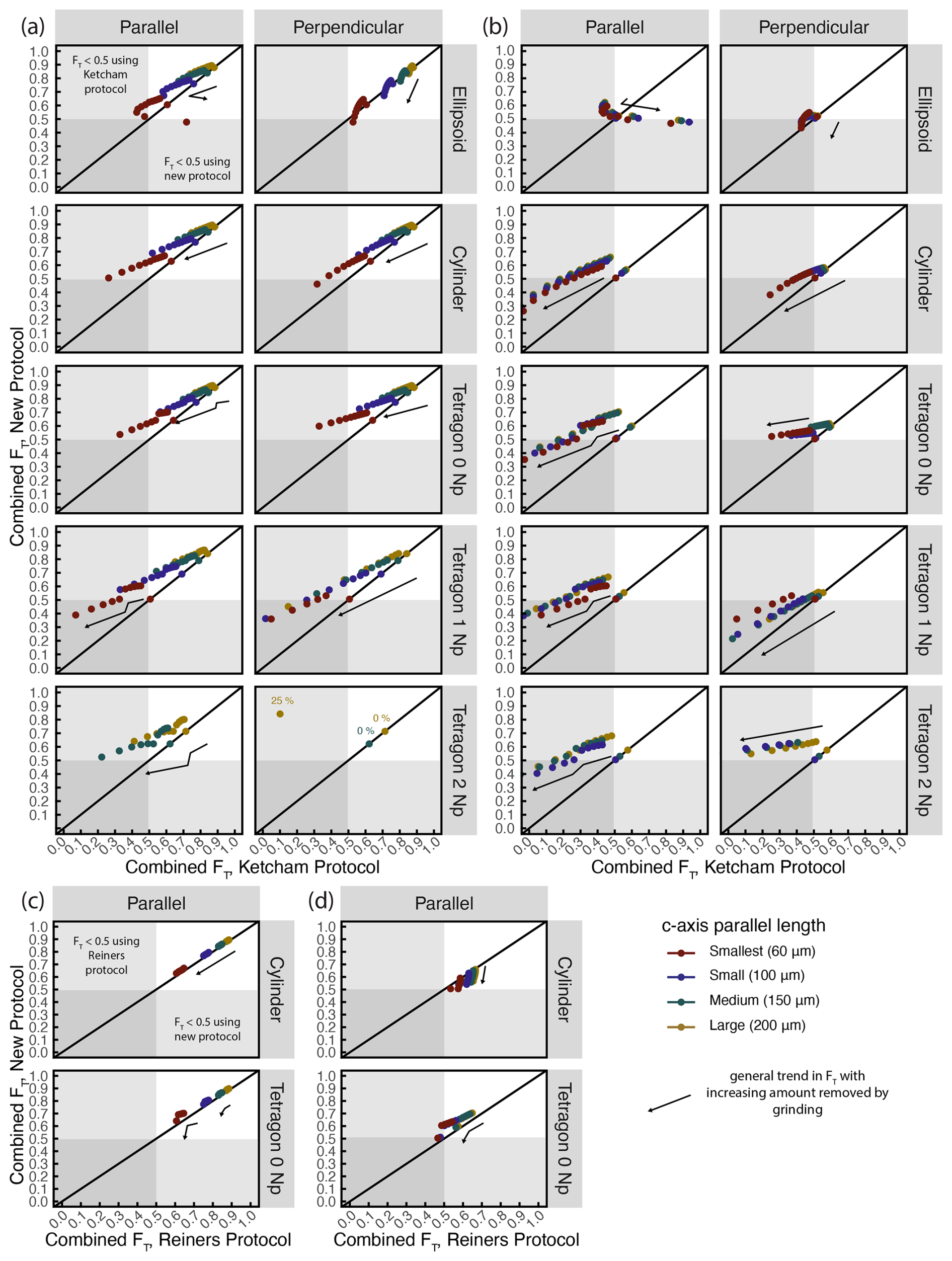
Figure 3Comparison between combined FT calculated using the new protocol and existing protocols. (a, b) Comparison with the protocol of Ketcham et al. (2011) for (a) equant grains (aspect ratio = 1, width ratio = 1) and (b) non-equant grains with minimum symmetry that meet requirements for whole-grain FT≥0.5. (c, d) Comparison with the protocol of Reiners et al. (2007) for (c) equant grains and (d) non-equant grains with minimum grain symmetry. See Fig. 2b for schematic variability between equant and non-equant grains. Note that the Reiners et al. (2007) protocol only applies to cylindrical and non-terminated tetragonal geometries and grinding depths ≤ 50 % of the original width. In all plots, color corresponds to size defined as the c-axis parallel length. Black arrows indicate the general trend of FT with increasing fraction of the grain removed through grinding. Gray shaded regions correspond to FT<0.5; these grains would typically be discarded from (U-Th)/He date interpretations.
FT values calculated using the new protocol were compared to existing FT protocols from Ketcham et al. (2011) and Reiners et al. (2007) (Fig. 3). Although the Ketcham et al. (2011) protocol is not designed for polished grains, it might be assumed that the difference in final FT value obtained by applying it might be negligible due to the application of the same polynomial coefficients in both methods. Here, the methods are compared to show that systematic biases are introduced when a whole-grain protocol is applied to polished grains that can result in limited utility of the dataset. This comparison was achieved by duplicating the synthetic dataset and setting the grinding depth g equal to 0 for all synthetic grains so that the code treated them as unpolished for calculating V, SAα, and FT. For equant grains (aspect and width ratios of 1; Fig. 2b), applying the whole-grain Ketcham et al. (2011) protocol results in FT values that are generally lower than the new protocol (Fig. 3a). This is expected: the Ketcham et al. (2011) protocol calculates SAα that is higher than the real polished SAα in all cases and, in the case of ellipsoids, calculates V that is significantly smaller than the real polished V. If the recommended 0.5 FT cutoff for accepting (U-Th)/He analyses is applied (e.g., Flowers et al., 2022b; Ketcham et al., 2011) to the polished fragments, use of the Ketcham et al. (2011) protocol would result in rejection of more ellipsoid, cylindrical, and terminated tetragonal grains than the new protocol, while more non-terminated tetragonal grains would be kept. This is because the only difference between the two protocols for non-terminated tetragonal grains is the inclusion of the polished face in SAα. For non-equant grains with varying degrees of symmetry (Fig. 2b), both protocols result in the rejection of most grain fragments (Fig. 3b), but the Ketcham et al. (2011) protocol results in more total rejections due to its inaccurate estimates of V and SAα. This is important for real datasets in which grain aspect and width ratios can be expected to vary widely and rarely match the equant case. By taking grinding and polishing into account, the new protocol results in FT values that reflect the true SAα and V of the measured grain fragment and are more likely to meet the criteria for being accepted.
The Reiners et al. (2007) protocol uses V and SAα of grain fragments with the FT formulas and polynomial coefficients of Farley (2002), but it applies only to cylindrical and non-terminated tetragonal grain geometries polished less than halfway through the original width of the crystal. For equant grains (Fig. 3c), the synthetic FT results of the Reiners et al. (2007) protocol are almost identical to the new protocol, with all FT values > 0.5. In these cases, the calculation of SAα and V are the same between the two methods, and any discrepancy is the result of differences between the polynomial coefficients used. However, systematic offsets related to grain geometry appear when comparing FT for cylindrical non-equant grains with less symmetry (Fig. 3d). For cylindrical grains, the Reiners et al. (2007) protocol results in higher FT values than the new protocol reflecting that the Reiners et al. (2007) protocol assumes grains are true cylinders with equant a and b semi-axes. This results in underestimates of SAα and V compared to the new protocol which treats cylinders as prisms with ellipsoidal pinacoid terminations. For tetragonal grains, FT values calculated using the new protocol are larger than values calculated using the Reiners et al. (2007) protocol. Tetragonal SAα and V are calculated using the same formulas regardless of protocol, so differences arise solely from the difference in polynomial coefficients. Although there is not a significant difference in the number of grain fragments with FT>0.5 between the new and Reiners protocols, the addition of ellipsoid grains and the greater range of grinding depths covered under the new protocol makes it an improvement over the existing Reiners et al. (2007) method.
The new protocol covers crystal morphologies commonly observed in the detrital zircon record and suggests grain size limits to guide selection of real grains for analyses involving polishing. For detrital zircon studies, grains are likely to be large due to grain size bias arising from abrasion during sedimentary transport (e.g., Fig. S1 in the Supplement), and size is generally less of a consideration for choosing grains. However, for other applications, in which a greater range of grain size is present, choice of grain targets will need to consider size, as in conventional whole-grain (U-Th)/He applications (e.g., Reiners and Farley, 2001). For thin, needle-like morphologies (Fig. 3b and d), grains with long axes < 150 are less likely to result in FT>0.5 and then only when ground < 55 % of the original grain width. When grain aspect ratios are higher, long axis length can be shorter to include grains with c-axis parallel lengths < 100 µm (Fig. 3a and c). However, for the smallest grains, care must still be taken to remove minimal material through grinding in order for FT values to be above 0.5.
An example of the applicability of the new protocol to detrital zircon datasets is provided in the Supplement. The new protocol can also be applied to certain non-sedimentary applications, though additional work is needed to accurately account for polishing tetragonal grains with terminations, such as those that are commonly found in igneous and metamorphic rocks.
To combine (U-Th)/He dates with the maximum additional same-grain data, methods for calculating grain V and (U-Th)/He data derived from V must account for the grinding and polishing of grains necessary for many in situ analyses. Previous work has provided protocols to calculate some derived data, mainly FT corrections, for some, but not all, grinding conditions. In particular, parent isotope concentrations and eU have previously been ignored. The protocol presented here provides a means to obtain V, SAα, and all data derived from these values, including FT and eU, regardless of original grain geometry and polishing conditions. For a suite of synthetic zircon, the new protocol behaves as expected for grains that meet recommended grain size requirements for whole-grain analyses and have ellipsoidal, cylindrical, or non-terminated tetragonal original grain morphologies. This makes the new protocol well suited to applications involving detrital zircon, which generally include these grain morphologies and large grains. Additional work is needed to adapt existing protocols or create new ones for cases involving tetragonal grains with pyramidal terminations. (U-Th)/He datasets are usually small and may be limited by other grain selection factors that reduce the population of suitable grains for a given sample; this makes it especially important to maximize the number of grains with usable FT values. The new protocol presented here achieves this through more accurate calculation of grain V and SAα for polished grain fragments used in the calculation of FT. Even for cases where prior methods for calculating FT for ground and polished grains (e.g., Reiners et al., 2007) apply, the new protocol is still an improvement, as it provides the full set of recommended reporting data (e.g., Flowers et al., 2022a). The new protocol includes calculation of all data derived from V (eU, parent isotope concentrations, and RFT) and assigns uncertainty following current recommendations for zircon (Zeigler et al., 2024). The comprehensive nature of the new protocol enables the incorporation of polished grain (U-Th)/He dates into existing workflows for (U-Th)/He date interpretation and thermal history modeling.
A1 Ellipsoid volume and alpha-ejection surface area
The ellipsoid semi-axes (a, b, and c) and polished surface semi-axes (aP, bP, and cP) are related to 2D grain measurements L1, L2, W1, W2, LP, WP, and g, as given in Table 1 and shown in Fig. 1b for each polishing orientation and depth. The ellipsoid coefficient (p) used in the calculation of SAα is 1.6075 (Ketcham et al., 2011). When the grain is polished perpendicular to the c axis or polished parallel to the c axis and more than halfway through the original c-axis perpendicular width (2), the grain is treated as half a symmetric ellipsoid broken perpendicular or parallel to the c axis, and V and SAα are calculated using formulas for half an ellipsoid Eqs. (A1) and (A2).
When the grain is polished parallel to the c axis and less than halfway through the original width (), V and SAα are calculated using Eqs. (A3) and (A4), which combine the estimated V and surface area of the whole original grain and the removed portion of the grain approximated as half a symmetric ellipsoid broken parallel to the c axis.
A2 Cylinder volume and alpha-ejection surface area
“Cylinders” can more accurately be represented as prisms with height (h) and ellipsoidal, rather than circular, pinacoid terminations with semi-axes a and b (Fig. 1b). V and SAα are calculated using the area of an ellipse (πab) and Ramanujan's formula for the perimeter of an ellipse (Eq. A5).
Semi-axes of the ellipsoid cross-section are denoted as a and b, k is defined as , and h is the height or length of the cylinder. The semi-axes are related to the 2D grain measurements and g depending on the degree of polishing, as given in Table 1. When the grain is polished perpendicular to the c axis, the grain is treated as half a symmetric prism broken perpendicular to the c axis, and V and SAα are calculated using Eqs. (A6) and (A7).
When the grain is polished parallel to the c axis and more than halfway through the original width (), V and SAα are calculated using Eqs. (A8) and (A9), which treat the fragment as half of a cylinder.
When the grain is polished parallel to the c axis and less than halfway (), V and SAα are calculated using Eqs. (A10) and (A11), which combine the estimated V and surface area of the whole original grain and the removed portion of the grain approximated as half a symmetric prism broken parallel to the c axis.
A3 Tetragon volume and alpha-ejection surface area
The tetragon axes (a, b, and c) are related to 2D grain measurements (L1, L2, W1, W2, and g), as given in Table 1 and shown in Fig. 1b for each polishing orientation and depth. Np is the number of pyramidal terminations (0, 1, or 2). When the grain is polished perpendicular to the c axis, the grain is treated as half a symmetric prism broken perpendicular to the c axis, and V and SAα are calculated using Eqs. (A12) and (A13).
When the grain is polished parallel to the c axis and more than halfway (), the grain is treated as half a symmetric prism broken parallel to the c axis, and V and SAα are calculated using Eqs. (A14) and (A15).
When the grain is polished parallel to the c axis and less than halfway (), V and SAα are calculated using Eqs. (A16) and (A17), which combine the estimated V and surface area of the whole original grain and the removed portion of the grain, which is approximated as half a symmetric prism broken parallel to the c axis.
A4 Mass, parent isotope concentrations, and eU
M is calculated assuming an average zircon density g µm−3 using Eq. (A18) and inherits uncertainty from V.
Parent isotope concentrations for uranium (U), thorium (Th), and samarium (Sm) in ppm are calculated from parent isotope masses in ng and total M using Eq. (A19). Parent isotope concentration uncertainty is propagated from the total analytical uncertainty on the ng measurements and M uncertainty inherited from V.
eU is calculated using Eq. (A9) from Cooperdock et al. (2019), Eq. (A20) below. Uncertainty on eU is propagated from uncertainties on the U, Th, and Sm concentrations combining total analytical uncertainty and V uncertainty.
A5 FT and RFT
FT values are calculated using the weighted mean stopping distances Sx of an alpha particle for a given parent isotope decay chain (15.55, 18.05, 18.43, and 4.76 µm for 238U, 235U, 232Th, and 147Sm, respectively; Ketcham et al., 2011), RSV dependent on the crystal volume and ejection surface area (Eq. 2), and geometry-specific FT equations from Ketcham et al. (2011) (Eqs. A21–A23 below). Equation (A22) for cylinders has been modified from Ketcham et al. (2011) to be in terms of RSV and h rather than r and h.
For ellipsoidal grains, FT is given by Eq. (A21):
For cylindrical grains, FT is given by Eq. (A22):
For tetragonal grains, FT is given by Eq. (A23). If the grain is polished perpendicular to the c axis, c from Table 1 is multiplied by 2 in Eq. (A23). If the grain is polished parallel to the c axis, b from Table 1 is multiplied by 2.
Combined FT is calculated for each grain using equations from Cooperdock et al. (2019) and activities for 238U and 232Th and A238 and A232, respectively (Eqs. A24–A26).
RFT is calculated using Eq. (6) from Cooperdock et al. (2019) and related equations (Eqs. A27–A29).
An R script to apply the protocol presented in this work is available with potential future updates on GitHub (https://github.com/Barra-Peak/polished-ZHe-derived-values, last access: 28 October 2025). A static version of all code scripts and data used to produce the results presented here is available in repository form (Peak, 2025). All data used to evaluate the protocol are also included in Tables S1 and S2 in the Supplement.
The supplement related to this article is available online at https://doi.org/10.5194/gchron-7-571-2025-supplement.
The author has declared that there are no competing interests.
Publisher's note: Copernicus Publications remains neutral with regard to jurisdictional claims made in the text, published maps, institutional affiliations, or any other geographical representation in this paper. While Copernicus Publications makes every effort to include appropriate place names, the final responsibility lies with the authors. Views expressed in the text are those of the authors and do not necessarily reflect the views of the publisher.
Spencer Zeigler proofread the R script and made suggestions to improve code efficiency. Conversations with Rebecca Flowers improved the clarity of early versions of the manuscript. Christoph Glotzbach, John He, and two anonymous reviewers provided comprehensive feedback and suggestions to revise the manuscript. Rich Ketcham provided additional helpful feedback on manuscript revisions, particularly on the discussion of the synthetic dataset. Shigeru Sueoka provided editorial support.
This paper was edited by Shigeru Sueoka and reviewed by Christoph Glotzbach, John He, and two anonymous referees.
Cooperdock, E. H. G., Ketcham, R. A., and Stockli, D. F.: Resolving the effects of 2-D versus 3-D grain measurements on apatite (U-Th)g/gHe age data and reproducibility, Geochronology, 1, 17–41, https://doi.org/10.5194/gchron-1-17-2019, 2019.
Danišík, M., McInnes, B. I. A., Kirkland, C. L., McDonald, B. J., Evans, N. J., and Becker, T.: Seeing is believing: Visualization of He distribution in zircon and implications for thermal history reconstruction on single crystals, Sci. Adv., 3, 1–9, https://doi.org/10.1038/s43247-025-02192-6, 2017.
Dröllner, M., Barham, M., and Kirkland, C. L.: Gaining from loss: Detrital zircon source-normalized α-dose discriminates first- versus multi-cycle grain histories, Earth Planet. Sc. Lett., 579, 117346, https://doi.org/10.1016/j.epsl.2021.117346, 2022.
Farley, K. A.: (U-Th)/He Dating: Techniques, Calibrations, and Applications, Rev. Mineral. Geochem., 47, 819–844, https://doi.org/10.2138/rmg.2002.47.18, 2002.
Flowers, R. M., Zeitler, P. K., Danišík, M., Reiners, P. W., Gautheron, C., Ketcham, R. A., Metcalf, J. R., Stockli, D. F., Enkelmann, E., and Brown, R. W.: (U-Th)/He chronology: Part 1. Data, uncertainty, and reporting, GSA Bull., 135, 104–136, https://doi.org/10.1130/B36266.1, 2022a.
Flowers, R. M., Ketcham, R. A., Enkelmann, E., Gautheron, C., Reiners, P. W., Metcalf, J. R., Danišík, M., Stockli, D. F., and Brown, R. W.: (U-Th)/He chronology: Part 2. Considerations for evaluating, integrating, and interpreting conventional individual aliquot data, GSA Bull., 135, 137–161, https://doi.org/10.1130/B36268.1, 2022b.
Glotzbach, C., Lang, K. A., Avdievitch, N. N., and Ehlers, T. A.: Increasing the accuracy of (U-Th(-Sm))/He dating with 3D grain modelling, Chem. Geol., 506, 113–125, https://doi.org/10.1016/j.chemgeo.2018.12.032, 2019.
Guenthner, W. R., Reiners, P. W., Ketcham, R. A., Nasdala, L., and Giester, G.: Helium diffusion in natural zircon: Radiation damage, anisotropy, and the interpretation of zircon (U-Th)/He thermochronology, Am. J. Sci., 313, 145–198, https://doi.org/10.2475/03.2013.01, 2013.
He, J. J. Y. and Reiners, P. W.: A revised alpha-ejection correction calculation for (U–Th)/He thermochronology dates of broken apatite crystals, Geochronology, 4, 629–640, https://doi.org/10.5194/gchron-4-629-2022, 2022.
Hourigan, J. K., Reiners, P. W., and Brandon, M. T.: U-Th zonation-dependent alpha-ejection in (U-Th)/He chronometry, Geochim. Cosmochim. Ac., 69, 3349–3365, https://doi.org/10.1016/j.gca.2005.01.024, 2005.
Ketcham, R. A., Gautheron, C., and Tassan-Got, L.: Accounting for long alpha-particle stopping distances in (U–Th–Sm)/He geochronology: Refinement of the baseline case, Geochim. Cosmochim. Ac., 75, 7779–7791, https://doi.org/10.1016/j.gca.2011.10.011, 2011.
Marsden, R. C., Danišík, M., Ito, H., Kirkland, C. L., Evans, N. J., Miura, D., Friedrichs, B., Schmitt, A. K., Uesawa, S., and Daggitt, M. L.: Considerations for double-dating zircon in secular disequilibrium with protracted crystallisation histories, Chem. Geol., 581, 120408, https://doi.org/10.1016/j.chemgeo.2021.120408, 2021.
Peak, B.A.: Barra-Peak/polished-ZHe-derived-values: polished_ZHe_derived_values_v2 (Version v2), Zenodo [code] [data set], https://doi.org/10.5281/zenodo.15642289, 2025.
Pickering, J., Matthews, W., Enkelmann, E., Guest, B., Sykes, C., and Koblinger, B. M.: Laser ablation (U-Th-Sm)/He dating of detrital apatite, Chem. Geol., 548, 119683, https://doi.org/10.1016/j.chemgeo.2020.119683, 2020.
Reiners, P. W. and Farley, K. A.: Influence of crystal size on apatite (U-Th)/He thermochronology: an example from the Bighorn Mountains, Wyoming, Earth Planet. Sc. Lett., 188, 413–420, https://doi.org/10.1016/S0012-821X(01)00341-7, 2001.
Reiners, P. W., Campbell, I. H., Nicolescu, S., Allen, C. M., Hourigan, J. K., Garver, J. I., Mattinson, J. M., and Cowan, D. S.: (U-Th)/(He-Pb) double dating of detrital zircons, Am. J. Sci., 305, 259–311, https://doi.org/10.2475/ajs.305.4.259, 2005.
Reiners, P. W., Thomson, S. N., McPhillips, D., Donelick, R. A., and Roering, J. J.: Wildfire thermochronology and the fate and transport of apatite in hillslope and fluvial environments, J. Geophys. Res.-Earth, 112, https://doi.org/10.1029/2007JF000759, 2007.
Zeigler, S. D., Metcalf, J. R., and Flowers, R. M.: A practical method for assigning uncertainty and improving the accuracy of alpha-ejection corrections and eU concentrations in apatite (U-Th)/He chronology, Geochronology, 5, 197–228, https://doi.org/10.5194/gchron-5-197-2023, 2023.
Zeigler, S. D., Baker, M., Metcalf, J. R., and Flowers, R. M.: The Geometric Correction Method for zircon (U–Th)/He chronology: correcting systematic error and assigning uncertainties to alpha-ejection corrections and eU concentrations, Geochronology, 6, 199–226, https://doi.org/10.5194/gchron-6-199-2024, 2024.
- Abstract
- Introduction
- Existing methods and limitations for polished grains
- Required measurements, grain classification, and calculation of values
- Evaluating the new protocol
- Conclusions
- Appendix A: Equations to calculate volume, alpha-ejection surface area, RSV, mass, parent isotope concentrations, eU, FT, and RFT
- Code and data availability
- Competing interests
- Disclaimer
- Acknowledgements
- Review statement
- References
- Supplement